U1003-ESP CAN C BUS PERFORMANCE
U1003-ESP CAN C BUS PERFORMANCE
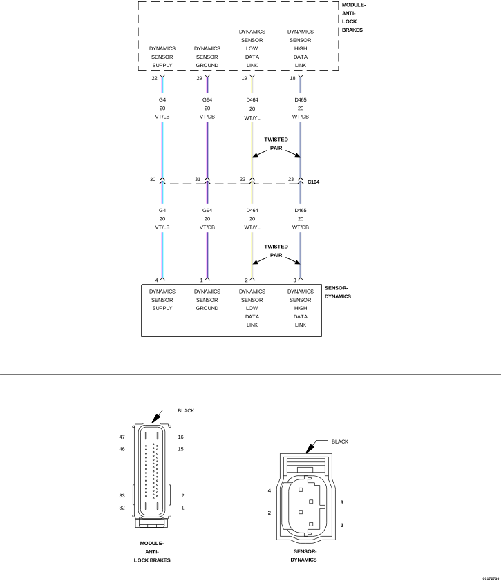 |
For a complete wiring diagram, refer to the Wiring Information.
-
When Monitored:
With the ignition on.
-
Set Condition:
If the Anti-Lock Brakes Module detects too many CAN Bus off events on the Dynamics Sensor Data Link circuits.
Possible Causes |
|---|
| WIRING HARNESS, TERMINAL, CONNECTOR DAMAGE |
| (D465) DYNAMICS SENSOR HIGH DATA LINK CIRCUIT SHORTED TO GROUND, VOLTAGE, OR OPEN |
| (D464) DYNAMICS SENSOR LOW DATA LINK CIRCUIT SHORTED TO GROUND, VOLTAGE, OR OPEN |
| DYNAMICS SENSOR |
| ANTI-LOCK BRAKE MODULE |
1. CHECK FOR A DTC U1003-ESP CAN C BUS PERFORMANCE
| NOTE: | This DTC must be active for the results of this test to be valid. |
| NOTE: | If present, diagnose and repair DTC U0125-LOST COMMUNICATION WITH DYNAMICS SENSOR before diagnosing this DTC. |
| 1. | Turn the ignition on. |
| 2. | With the scan tool, read and record DTCs. |
| 3. | With the scan tool, read and record Environmental Data to help identify the conditions in which the DTC was set. |
| 4. | With the scan tool, erase DTCs. |
| 5. | Start the engine. |
| NOTE: | Attempt to operate the vehicle under conditions similar to which the DTC was set. It may be necessary to test drive the vehicle within the DTC monitoring and set conditions in order for this DTC to set. |
| 6. | With the scan tool, read and record DTCs |
Does the scan tool display: U1003-ESP CAN C BUS PERFORMANCE?
Yes
- Go To 2
No
-
Perform the ABS INTERMITTENT CONDITION diagnostic procedure. (Refer to 28 - DTC-Based Diagnostics/MODULE, Antilock Brake (ABS)
- Standard Procedure).
2. CHECK THE WIRING HARNESS, TERMINALS, AND CONNECTORS
| NOTE: | The Sensor Cluster is the same as the Dynamics sensor. |
| 1. | Check the Dynamics Sensor installation and torque of the mounting bolts. |
| 2. | Visually inspect the related wiring harness. Look for any bruised, chafed, pierced, or partially broken wires. |
| 3. | Visually inspect the related wiring harness connectors. Look for broken, bent, pushed out, or corroded terminals. |
Were any problems found?
Yes
- Repair as necessary.
- Perform the ABS VERIFICATION TEST. (Refer to 28 - DTC-Based Diagnostics/MODULE, Antilock Brake (ABS) - Standard Procedure).
No
-
Go To 3
3. CHECK THE (D465) DYNAMICS SENSOR HIGH DATA LINK CIRCUIT FOR A SHORT TO VOLTAGE
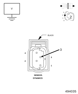 |
| 1. | Turn the ignition off. |
| 2. | Disconnect the Anti-Lock Brake Module harness connector. |
| 3. | Disconnect the Dynamics Sensor harness connector. |
| 4. | Turn the ignition on. |
| 5. | Measure the voltage of the (D465) Dynamics Sensor High Data Link circuit. |
Is there any voltage present?
Yes
- Repair the (D465) Dynamics Sensor High Data link circuit for a short to voltage.
- Perform the ABS VERIFICATION TEST. (Refer to 28 - DTC-Based Diagnostics/MODULE, Antilock Brake (ABS) - Standard Procedure).
No
-
Go To 4
4. CHECK THE (D465) DYNAMICS SENSOR HIGH DATA LINK CIRCUIT FOR A SHORT TO GROUND
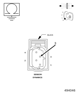 |
| 1. | Turn the ignition off. |
| 2. | Disconnect the Anti-Lock Brake Module harness connector. |
| 3. | Disconnect the Dynamics Sensor harness connector. |
| 4. | Measure the resistance between ground and the (D465) Dynamics Sensor High Data Link circuit. |
Is the resistance below 5.0 Ohms?
Yes
- Repair the (D465) Dynamics Sensor High Data link circuit for a short to ground.
- Perform the ABS VERIFICATION TEST. (Refer to 28 - DTC-Based Diagnostics/MODULE, Antilock Brake (ABS) - Standard Procedure).
No
-
Go To 5
5. CHECK THE (D465) DYNAMICS SENSOR HIGH DATA LINK CIRCUIT FOR AN OPEN
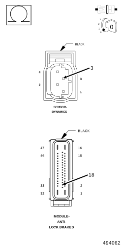 |
| 1. | Measure the resistance of the (D465) Dynamics Sensor High Data Link circuit. |
Is the resistance below 5.0 Ohms?
Yes
- Go To 6
No
- Repair the (D465) Dynamics Sensor High Data link circuit for an open.
-
Perform the ABS VERIFICATION TEST. (Refer to 28 - DTC-Based Diagnostics/MODULE, Antilock Brake (ABS)
- Standard Procedure).
6. CHECK THE (D464) DYNAMICS SENSOR LOW DATA LINK CIRCUIT FOR A SHORT TO VOLTAGE
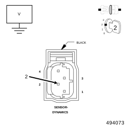 |
| 1. | Turn the ignition on. |
| 2. | Measure the voltage of the (D464) Dynamics Sensor Low Data Link circuit. |
Is there any voltage present?
Yes
- Repair the (D464) Dynamics Sensor Low Data link circuit for a short to voltage.
- Perform the ABS VERIFICATION TEST. (Refer to 28 - DTC-Based Diagnostics/MODULE, Antilock Brake (ABS) - Standard Procedure).
No
-
Go To 7
7. CHECK THE (D464) DYNAMICS SENSOR LOW DATA LINK CIRCUIT FOR A SHORT TO GROUND
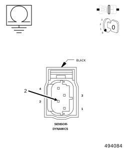 |
| 1. | Turn the ignition off. |
| 2. | Measure the resistance between ground and the (D464) Dynamics Sensor Low Data Link circuit. |
Is the resistance below 5.0 Ohms?
Yes
- Repair the (D464) Dynamics Sensor Low Data link circuit for a short to ground.
- Perform the ABS VERIFICATION TEST. (Refer to 28 - DTC-Based Diagnostics/MODULE, Antilock Brake (ABS) - Standard Procedure).
No
-
Go To 8
8. CHECK THE (D464) DYNAMICS SENSOR LOW DATA LINK CIRCUIT FOR AN OPEN
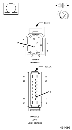 |
| 1. | Measure the resistance of the (D464) Dynamics Sensor Low Data link circuit. |
Is the resistance below 5.0 Ohms?
Yes
- Go To 9
No
- Repair the (D464) Dynamics Sensor Low Data link circuit for an open.
-
Perform the ABS VERIFICATION TEST. (Refer to 28 - DTC-Based Diagnostics/MODULE, Antilock Brake (ABS)
- Standard Procedure).
9. REPLACE DYNAMICS SENSOR & VERIFY IF DTC IS STILL ACTIVE
| 1. | Replace the Dynamics Sensor in accordance with the Service Information. Perform the ABS VERIFICATION TEST (Refer to 28 - DTC-Based Diagnostics/MODULE, Antilock Brake (ABS) - Standard Procedure) |
| 2. | Test drive the vehicle by turning the vehicle left or right in a curving manner at a velocity between 10 and 25 km/h (6 and 15 mph). |
| 3. | Park the vehicle. With the scan tool, read ABS DTCs. |
Does this DTC reset?
Yes
- Replace the Anti-Lock Brake Module in accordance with the Service Information.
-
Perform the ABS VERIFICATION TEST. (Refer to 28 - DTC-Based Diagnostics/MODULE, Antilock Brake (ABS)
- Standard Procedure).
No