MODULE, Hands Free (HFM)
- B143B-MICROPHONE 1 CIRCUIT LOW
- B143C-MICROPHONE 1 CIRCUIT HIGH
- U0010-CAN INTERIOR BUS
- U0141-LOST COMMUNICATION WITH IPM (FCM/TIPM)
- U0155-LOST COMMUNICATION WITH CLUSTER/CCN
- U0184-LOST COMMUNICATION WITH RADIO
B143B-MICROPHONE 1 CIRCUIT LOW
B143B-MICROPHONE 1 CIRCUIT LOW
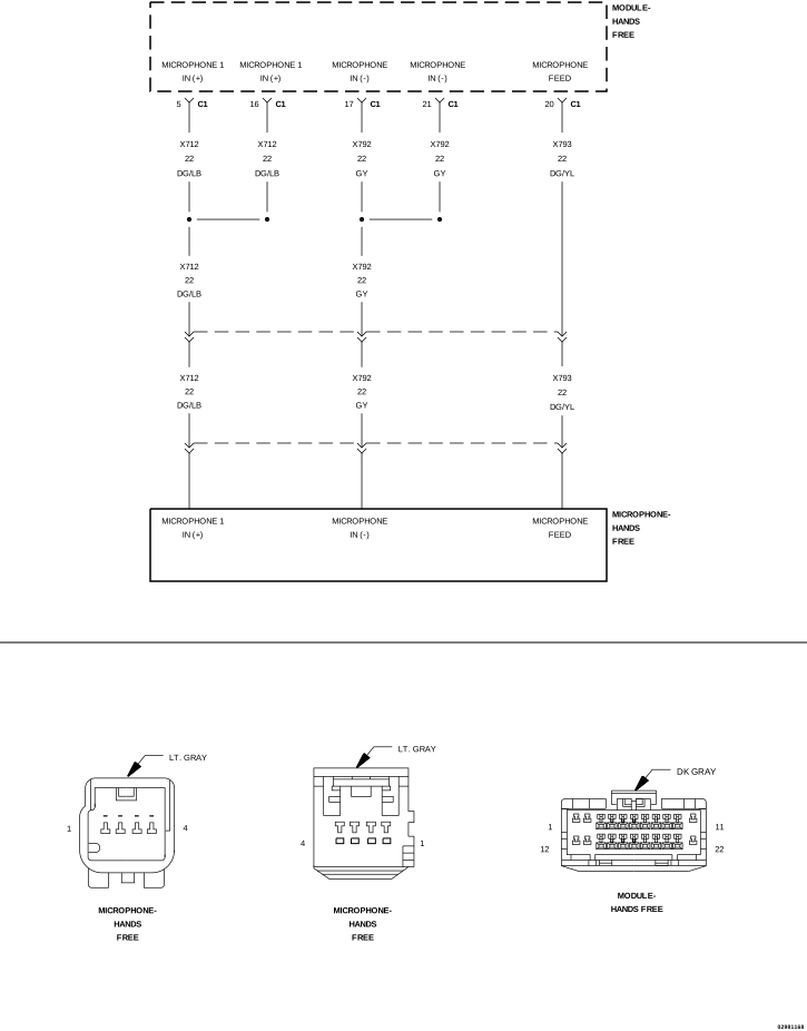 |
For a complete wiring diagram, refer to the Wiring Information.
-
When Monitored:
With the ignition on.
-
Set Condition:
The Hands Free Module (HFM) detects a short to ground or open on the (X712) Microphone 1 IN (+) circuit.
Possible Causes |
|---|
| (X712) MICROPHONE 1 IN (+) CIRCUIT OPEN |
| (X712) MICROPHONE 1 IN (+) CIRCUIT SHORTED TO GROUND |
| HANDS FREE MICROPHONE |
| HANDS FREE MODULE (HFM) |
| NOTE: | Verify the connection of the Rearview Mirror harness connector. |
| 1. | Turn the ignition on. |
| 2. | With the scan tool, read the active DTCs. |
Does the scan tool display B143B-MICROPHONE 1 CIRCUIT LOW as active?
Yes
- Go To 2
No
- Test complete, the condition or conditions that originally set this DTC are not present at this time. Using the wiring diagrams as a guide, check all related splices and connectors for signs of water intrusion, corrosion, pushed out or bent terminals and correct pin tension.
- Perform the BODY VERIFICATION TEST. (Refer to 28 - DTC-Based Diagnostics/MODULE, Totally Integrated Power (TIPM) - Standard Procedure).
2. CHECK THE HANDS FREE MICROPHONE
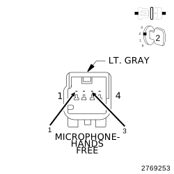 |
| 1. | Turn the ignition off. |
| 2. | Disconnect the Hands Free Microphone harness connector. |
| 3. | Connect a jumper wire between the (X793) Microphone Feed and the (X712) Microphone 1 IN (+) circuits. |
| 4. | Turn the ignition on. |
| 5. | With the scan tool, read the DTCs. |
| NOTE: | DTC B143C-MICROPHONE 1 CIRCUIT HIGH should display as active as a result of this test. |
Does the scan tool display B143B-MICROPHONE 1 CIRCUIT LOW as active?
Yes
- Go To 3
No
- Replace the Hands Free Microphone in accordance with the Service Information.
-
Perform the BODY VERIFICATION TEST. (Refer to 28 - DTC-Based Diagnostics/MODULE, Totally Integrated Power (TIPM)
- Standard Procedure).
3. CHECK FOR THE (X712) MICROPHONE 1 IN (+) CIRCUIT OPEN
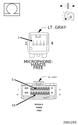 |
| 1. | Turn the ignition off. |
| 2. | Disconnect the Hands Free Module C1 harness connector. |
| 3. | Measure the resistance of the (X712) Microphone 1 IN (+) circuit between the Hands Free Microphone and Hands Free Module harness connectors. |
Is the resistance above 10K Ohms?
Yes
- Repair the (X712) Microphone 1 IN (+) circuit for an open.
- Perform the BODY VERIFICATION TEST. (Refer to 28 - DTC-Based Diagnostics/MODULE, Totally Integrated Power (TIPM) - Standard Procedure).
No
-
Go To 4
4. CHECK FOR THE (X712) MICROPHONE 1 IN (+) CIRCUIT SHORTED TO GROUND
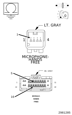 |
| 1. | Measure the resistance between ground and the (X712) Microphone 1 IN (+) circuit. |
Is the resistance below 10K Ohms?
Yes
- Repair the (X712) Microphone 1 IN (+) circuit for short to ground.
- Perform the BODY VERIFICATION TEST. (Refer to 28 - DTC-Based Diagnostics/MODULE, Totally Integrated Power (TIPM) - Standard Procedure).
No
- Replace the Hands Free Module in accordance with the Service Information.
-
Perform the BODY VERIFICATION TEST. (Refer to 28 - DTC-Based Diagnostics/MODULE, Totally Integrated Power (TIPM)
- Standard Procedure).
B143C-MICROPHONE 1 CIRCUIT HIGH
B143C-MICROPHONE 1 CIRCUIT HIGH
|
For a complete wiring diagram, refer to the Wiring Information.
-
When Monitored:
With the ignition on.
-
Set Condition:
The Hands Free Module (HFM) detects a short to voltage on the (X712) Microphone 1 IN (+) circuit.
Possible Causes |
|---|
| (X712) MICROPHONE 1 IN (+) CIRCUITS SHORTED TO VOLTAGE |
| HANDS FREE MICROPHONE |
| HANDS FREE MODULE (HFM) |
| NOTE: | Verify the connection of the Hands Free Microphone harness connector. |
| 1. | Turn the ignition on. |
| 2. | With the scan tool, read the active DTCs. |
Does the scan tool display B143C-MICROPHONE 1 CIRCUIT HIGH as active?
Yes
- Go To 2
No
- Test complete, the condition or conditions that originally set this DTC are not present at this time. Using the wiring diagrams as a guide, check all related splices and connectors for signs of water intrusion, corrosion, pushed out or bent terminals and correct pin tension.
- Perform the BODY VERIFICATION TEST. (Refer to 28 - DTC-Based Diagnostics/MODULE, Totally Integrated Power (TIPM) - Standard Procedure).
2. CHECK THE HANDS FREE MICROPHONE
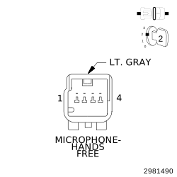 |
| 1. | Turn the ignition off. |
| 2. | Disconnect the Hands Free Microphone harness connector. |
| 3. | Turn the ignition on. |
| 4. | With the scan tool, read the active DTCs. |
Does the scan tool display B143C-MICROPHONE 1 CIRCUIT HIGH as active?
Yes
- Go To 3
No
- Replace the Hands Free Microphone in accordance with the Service Information.
-
Perform the BODY VERIFICATION TEST. (Refer to 28 - DTC-Based Diagnostics/MODULE, Totally Integrated Power (TIPM)
- Standard Procedure).
3. CHECK THE (X712) MICROPHONE 1 IN (+) CIRCUIT FOR A SHORT TO VOLTAGE
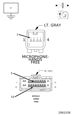 |
| 1. | Turn the ignition off. |
| 2. | Disconnect the Hands Free Module C1 harness connector. |
| 3. | Turn the ignition on. |
| 4. | Measure the voltage of the (X712) Microphone circuit. |
Is the voltage above 1.0 volt?
Yes
- Repair the (X712) Microphone circuit for a short to voltage.
- Perform the BODY VERIFICATION TEST. (Refer to 28 - DTC-Based Diagnostics/MODULE, Totally Integrated Power (TIPM) - Standard Procedure).
No
- Replace the Hands Free Module in accordance with the Service Information.
- Perform the BODY VERIFICATION TEST. (Refer to 28 - DTC-Based Diagnostics/MODULE, Totally Integrated Power (TIPM) - Standard Procedure).
U0010-CAN INTERIOR BUS
U0010-CAN INTERIOR BUS
For a complete wiring diagram, refer to the Wiring Information.
-
When Monitored:
Continuously when the ignition is on.
Battery voltage between 10 and 16 volts.
Ignition Off Draw (IOD) fuse installed.
-
Set Condition:
The controller detects a short to ground on the CAN Interior Bus (125K)(+) circuit or a short to voltage on the CAN Interior Bus (125K)(-) circuit.
Possible Causes |
|---|
| (D265) CAN INTERIOR BUS(+) (125k) CIRCUIT SHORTED TO VOLTAGE |
| (D264) CAN INTERIOR BUS(-) (125k) CIRCUIT SHORTED TO GROUND |
| (D264) CAN INTERIOR BUS(-) (125k) CIRCUIT SHORTED TO THE (D265) CAN INTERIOR BUS(+) (125k) CIRCUIT |
| TOTALLY INTEGRATED POWER MODULE (TIPM) |
| ANY CAN INTERIOR BUS MODULE |
VERIFY DIAGNOSTIC TROUBLE CODE (DTC) IS ACTIVE
| NOTE: | Make sure the IOD fuse is installed and battery voltage is between 10 and 16 volts before proceeding. |
| 1. | Using the scan tool, read active DTCs. |
Is this DTC active?
Yes
- (Refer to 28 - DTC-Based Diagnostics/MODULE, Totally Integrated Power (TIPM) - Diagnosis and Testing) and perform the U0010-CAN Interior Bus diagnostic procedure.
No
- (Refer to 29 - Non-DTC Diagnostics/Communication - Diagnosis and Testing) and perform the Stored Lost Communication DTCs diagnostic procedure.
U0141-LOST COMMUNICATION WITH IPM (FCM/TIPM)
U0141-LOST COMMUNICATION WITH IPM (FCM/TIPM)
For a complete wiring diagram, refer to the Wiring Information.
-
When Monitored:
Continuously when the ignition is on.
The battery voltage between 10.0 and 16.0 Volts.
Ignition Off Draw (IOD) fuse installed.
Totally Integrated Power Module (TIPM) is configured correctly.
-
Set Condition:
Bus messages not received from the Totally Integrated Power Module (TIPM) for approximately two to five seconds.
Possible Causes |
|---|
| CAN BUS CIRCUITS OPEN OR SHORTED |
| DTCS RELATED TO BATTERY VOLTAGE, IGNITION, OR VIN MESSAGES |
| TOTALLY INTEGRATED POWER MODULE POWER AND GROUND |
| TIPM NOT CONFIGURED CORRECTLY |
| TOTALLY INTEGRATED POWER MODULE (TIPM) |
| MODULE THAT SET THIS DTC |
VERIFY DTC IS ACTIVE
| NOTE: | Make sure the IOD fuse is installed and the battery is fully charged before proceeding. |
| 1. | Turn the ignition on. |
| 2. | With the scan tool, read active DTCs. |
Is this DTC active?
Yes
- (Refer to 28 - DTC-Based Diagnostics/MODULE, Totally Integrated Power (TIPM) - Diagnosis and Testing) and perform the U0141-Lost Communication with IPM (FCM/TIPM) diagnostic procedure.
No
- (Refer to 29 - Non-DTC Diagnostics/Communication - Diagnosis and Testing) and perform the Stored Lost Communication DTCs diagnostic procedure.
U0155-LOST COMMUNICATION WITH CLUSTER/CCN
U0155-LOST COMMUNICATION WITH CLUSTER/CCN
For a complete wiring diagram, refer to the Wiring Information.
-
When Monitored:
Continuously when the ignition is on.
The battery voltage is between 10 and 16 volts.
Ignition Off Draw (IOD) fuse installed.
Totally Integrated Power Module (TIPM) is configured correctly.
-
Set Condition:
Bus messages not received from the Instrument Cluster (CCN) for approximately two to five seconds.
Possible Causes |
|---|
| CAN BUS CIRCUITS OPEN OR SHORTED |
| DTCS RELATED TO BATTERY VOLTAGE, IGNITION, OR VIN MESSAGES |
| INSTRUMENT CLUSTER POWER AND GROUND |
| TIPM NOT CONFIGURED CORRECTLY |
| INSTRUMENT CLUSTER (CCN) |
| MODULE THAT SET THIS DTC |
VERIFY THE DIAGNOSTIC TROUBLE CODE (DTC) IS ACTIVE
| NOTE: | Make sure the IOD fuse is installed and the battery is fully charged before proceeding. |
| 1. | Turn the ignition on. |
| 2. | With the scan tool, read active DTCs. |
Is this DTC active?
Yes
- (Refer to 28 - DTC-Based Diagnostics/MODULE, Totally Integrated Power (TIPM) - Diagnosis and Testing) and perform the U0155-Lost Communication with Cluster/CCN diagnostic procedure.
No
- (Refer to 29 - Non-DTC Diagnostics/Communication - Diagnosis and Testing) and perform the Stored Lost Communication DTCs diagnostic procedure.
U0184-LOST COMMUNICATION WITH RADIO
U0184-LOST COMMUNICATION WITH RADIO
For a complete wiring diagram, refer to the Wiring Information.
-
When Monitored:
Continuously when the ignition is on.
Battery voltage between 10 and 16 volts.
Ignition Off Draw (IOD) fused installed.
Totally Integrated Power Module (TIPM) is configured correctly.
-
Set Condition:
Bus messages not received from the Radio for approximately two to five seconds.
Possible Causes |
|---|
| CAN BUS CIRCUITS OPEN OR SHORTED |
| DTCS RELATED TO BATTERY VOLTAGE, IGNITION, OR VIN MESSAGES |
| RADIO POWER AND GROUND |
| TIPM NOT CONFIGURED CORRECTLY |
| RADIO |
| MODULE THAT SET THIS DTC |
VERIFY THE DIAGNOSTIC TROUBLE CODE (DTC) IS ACTIVE
| NOTE: | Make sure the IOD fuse is installed and the battery is fully charged before proceeding. |
| 1. | Turn the ignition on. |
| 2. | With the scan tool, read the active DTCs. |
Is this DTC active?
Yes
- (Refer to 28 - DTC-Based Diagnostics/MODULE, Totally Integrated Power (TIPM) /Diagnosis and Testing) and perform the U0184-87–Lost Communication with Radio — Missing Message diagnostic procedure.
No
- (Refer to 29 - Non-DTC Diagnostics/Communication - Diagnosis and Testing) and perform the Stored Lost Communication DTCs diagnostic procedure.