2012 Jeep Wrangler JK Factory Service Manual 28 - DTC-Based Diagnostics

P0008-ENGINE POSITION SYSTEM PERFORMANCE (BANK 1)

P0008-ENGINE POSITION SYSTEM PERFORMANCE (BANK 1)


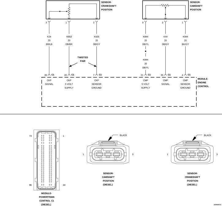
For a complete wiring diagram, refer to the Wiring Information.


Possible Causes

(K44) ERRATIC CAM POSITION SENSOR 1 SIGNAL
(K24) ERRATIC CRANKSHAFT POSITION SENSOR SIGNAL
CAMSHAFT POSITION SENSOR TONE WHEEL/PULSE RING
CRANKSHAFT POSITION SENSOR MAGNETIC RING
CAMSHAFT POSITION SENSOR
CRANKSHAFT POSITION SENSOR
TIMING GEAR MISALIGNMENT/INCORRECT VALVE TIMING

Always perform the Pre-Diagnostic Troubleshooting procedure before proceeding. (Refer to 28 - DTC-Based Diagnostics/MODULE, Powertrain Control (PCM) - Standard Procedure).


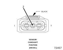
1. CHECKING THE (K44) CMP SIGNAL WITH A LAB SCOPE


1. Using a lab scope, backprobe the (K44) CMP Signal circuit at the CMP Sensor harness connector.

CAUTION:

Use only approved back probe tools when back probing a connector so as not to cause damage to the terminals or insulation of the connector. Damage to the terminals can cause poor terminal contact or retention. Damage to the insulation can introduce corrosion due to water infiltration.

2. Start the engine.
3. Observe the lab scope screen.


NOTE: The CMP Sensor is a hall-effect type sensor that produces a 5-Volt digital (square wave) signal.


Are there any irregular or missing signals?

Yes


No


2. CMP WIRE HARNESS INSPECTION


1. Turn the ignition off.
2. Visually inspect the related wire harness. Look for any chafed, pierced, pinched, or partially broken wires.
3. Visually inspect the related wire harness connectors. Look for broken, bent, pushed out, or corroded terminals.
4. Make sure the Camshaft Position Sensor is properly installed and the mounting bolt(s) are torqued to their proper specification.
5. Perform any TSBs that may apply.


Were any of the above conditions present?

Yes


No


3. TONE WHEEL/PULSE RING INSPECTION


1. Remove the Camshaft Position Sensor.
2. Inspect the Tone Wheel/Pulse Ring for damage, foreign material, or excessive movement.


Were any problems found?

Yes


No


4. ERRATIC CMP SIGNAL


1. Turn the ignition off.
2. Remove the lab scope probe.
3. Inspect the CMP Sensor connector and harness connector, and inspect the PCM connector and harness connector for loose, bent, corroded, or pushed out pins/terminals.
4. Inspect the related wire harness and the splices in the CMP circuit.
5. Ignition on, engine not running.
6. With scan tool, erase DTCs.
7. Start the engine.
8. Gently tap on and wiggle the Cam Position Sensor.


Did this DTC return?

Yes


No


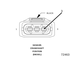
5. CHECK THE (K24) CKP SIGNAL WITH A LAB SCOPE


1. Turn the ignition off.
2. With a lab scope, backprobe the (K24) CKP Signal circuit at the CKP harness connector.

CAUTION:

Use only approved back probe tools when back probing a connector so as not to cause damage to the terminals or insulation of the connector. Damage to the terminals can cause poor terminal contact or retention. Damage to the insulation can introduce corrosion due to water infiltration.

3. Start the engine.
4. Observe the lab scope screen.


NOTE: The CKP Sensor is a hall-effect type sensor that produces a 5-Volt digital (square wave) signal.


Are there any irregular or missing signals?

Yes


No


6. CKP WIRE HARNESS INSPECTION


1. Turn the ignition off.
2. Visually inspect the related wire harness. Look for any chafed, pierced, pinched, or partially broken wires.
3. Visually inspect the related wire harness connectors. Look for broken, bent, pushed out, or corroded terminals.
4. Make sure the Crankshaft Position Sensor is properly installed and the mounting bolt(s) are torqued to their proper specification.
5. Perform any Technical Service Bulletins (TSBs) that may apply.


Were any of the above conditions present?

Yes


No


7. MAGNETIC RING INSPECTION


1. Remove the Crankshaft Position Sensor.
2. Inspect the Magnetic Ring for damage, foreign material, or excessive movement.


Were any problems found?

Yes


No


8. ERRATIC CKP SIGNAL


NOTE: The conditions that set this DTC are not present at this time. The following test may help in identifying the intermittent condition.
1. Turn the ignition off.
2. Remove the lab scope probe.
3. Inspect the CKP Sensor connector and harness connector, and inspect the PCM connector and harness connector for loose, bent, corroded, or pushed out pins/terminals.
4. Inspect the related wire harness and the splices in the CKP circuit.
5. Ignition on, engine not running.
6. With scan tool, erase DTCs.
7. Start the engine.
8. Gently tap on and wiggle the CKP Sensor.


Did the DTC return?

Yes


No