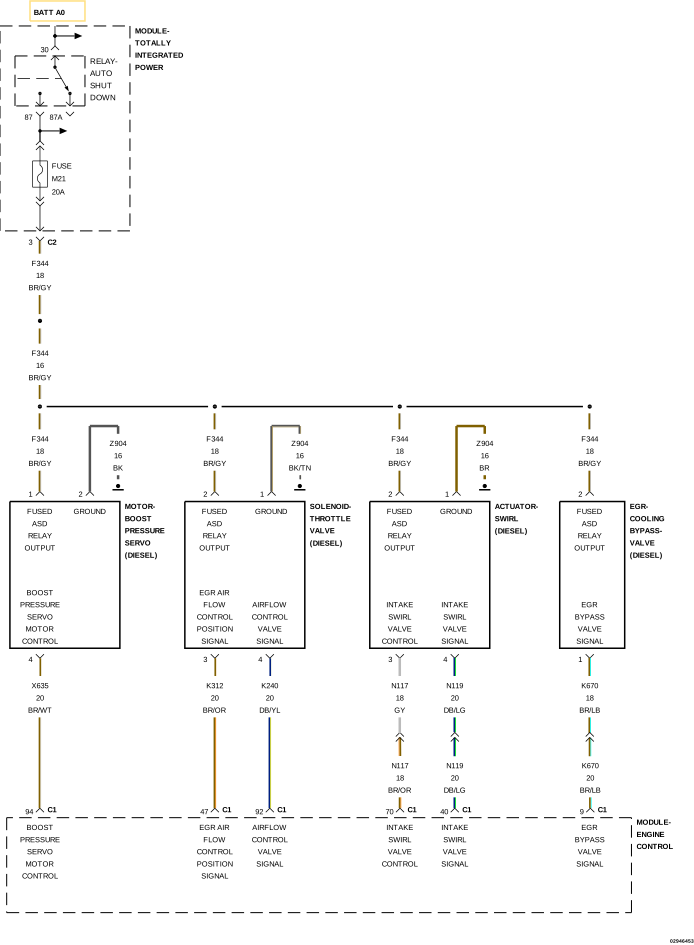
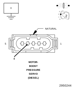
For a complete wiring diagram, refer to the Wiring Information.
Theory of Operation
The Boost Pressure Actuator is an electrically operated DC motor designed to regulate the boost pressure output of the Turbocharger. The Boost Pressure Actuator is mounted to the side of the Turbocharger assembly. The Boost Pressure Actuator receives 12 Volt power from the Totally Integrated Power Module (TIPM) and a duty-cycle control signal from the Powertrain Control Module (PCM). When this fault is active the EGR System, DPF Regeneration, and Boost Pressure Actuator are disabled. The engine will also experience a torque reduction.
When Monitored:
With the ignition on and the Boost Pressure Actuator command on.
Set Condition:
The Powertrain Control Module (PCM) detects that the (X635) Boost Pressure Actuator Control circuit voltage is high for 0.5 second.
Possible Causes
(X635) BOOST PRESSURE ACTUATOR CONTROL CIRCUIT SHORTED TO VOLTAGE
(X635) BOOST PRESSURE ACTUATOR CONTROL SHORTED TO THE (F344) FUSED ASD RELAY OUTPUT CIRCUIT
3.
CHECK THE (X635) BOOST PRESSURE ACTUATOR CONTROL FOR A SHORT TO THE (F344) FUSED ASD RELAY OUTPUT CIRCUIT
1.
Turn the ignition off.
2.
Disconnect the PCM C1 harness connector.
3.
Disconnect the TIPM C2 harness connector.
4.
Remove the jumper wire and install the ASD Relay.
5.
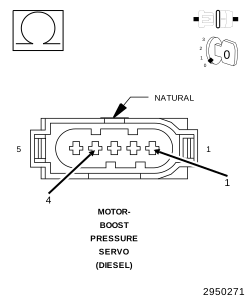
Measure the resistance between the (X635) Boost Pressure Actuator Control circuit and the (F344) Fused ASD Relay Output circuit at the Boost Pressure Actuator harness connector.
Using the wiring diagram/schematic as a guide, inspect the wiring and connectors between the Boost Pressure Actuator and the Powertrain Control Module (PCM).
2.
Look for any chafed, pierced, pinched, or partially broken wires.
3.
Look for broken, bent, pushed out or corroded terminals.
4.
Perform any Technical Service Bulletins that may apply.