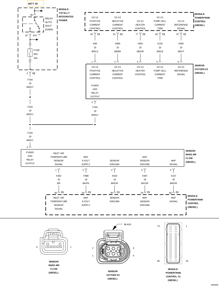
For a complete wiring diagram, refer to the Wiring Information.
Theory of Operation
The Intake Air Temperature Sensor 1 is combined with the Mass Air Flow Sensor. It is located on the Air Cleaner Box and is used to monitor the temperature of the air entering the intake system. The Intake Air Temperature Sensor operates as a typical two wire sensor. It receives a 5-Volt signal on the (K362) Intake Air Temperature Sensor Signal circuit and uses the (K916) Sensor Ground circuit. When this fault code is active the EGR system will be disabled.
When Monitored:
With the ignition on.
Set Condition:
The PCM detects that the (K157) Mass Air Flow Sensor Signal has exceeded it's maximum threshold for 2.5 seconds.
Possible Causes
INTAKE/EXHAUST SYSTEM PROBLEMS
HIGH RESISTANCE IN THE (K157) MASS AIR FLOW SENSOR SIGNAL CIRCUIT
HIGH RESISTANCE IN THE (K957) MASS AIR FLOW SENSOR GROUND CIRCUIT
If any Sensor Reference DTCs are present, or if there are any other MAF Sensor DTCs present, perform the applicable diagnostic procedure before continuing with this test procedure.
1.
Ignition on, engine not running.
2.
With the scan tool, Clear DTCs in the PCM.
3.
Start the engine and allow it to reach normal operating temperature.
3.
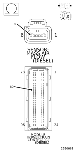
CHECK FOR HIGH RESISTANCE IN THE (K157) MASS AIR FLOW SENSOR SIGNAL CIRCUIT
1.
Turn the ignition off.
2.
Disconnect the Mass Air Flow Sensor harness connector.
3.
Disconnect the PCM C1 harness connector.
4.
Measure the resistance of the (K157) Mass Air Flow Sensor Signal circuit between the Mass Air Flow Sensor harness connector and the PCM C1 harness connector.
4.
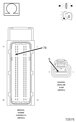
CHECK FOR HIGH RESISTANCE IN THE (K957) MASS AIR FLOW SENSOR GROUND CIRCUIT
1.
Measure the resistance of the (K957) Mass Air Flow Sensor Ground circuit between the Mass Air Flow Sensor harness connector and the PCM C1 harness connector.
Using the wiring diagram/schematic as a guide, inspect the wiring and connectors between the Mass Air Flow Sensor and the Powertrain Control Module (PCM).
2.
Look for any chafed, pierced, pinched, or partially broken wires.
3.
Look for broken, bent, pushed out or corroded terminals.
4.
Monitor the scan tool data relative to this circuit and wiggle test the wiring and connectors.
5.
Look for the data to change or for the DTC to reset during the wiggle test.
6.
Refer to any Technical Service Bulletins that may apply.