P0133-O2 SENSOR 1/1 SLOW RESPONSE
P0133-O2 SENSOR 1/1 SLOW RESPONSE
Special Tools: Click to display a list of tools used in this procedure

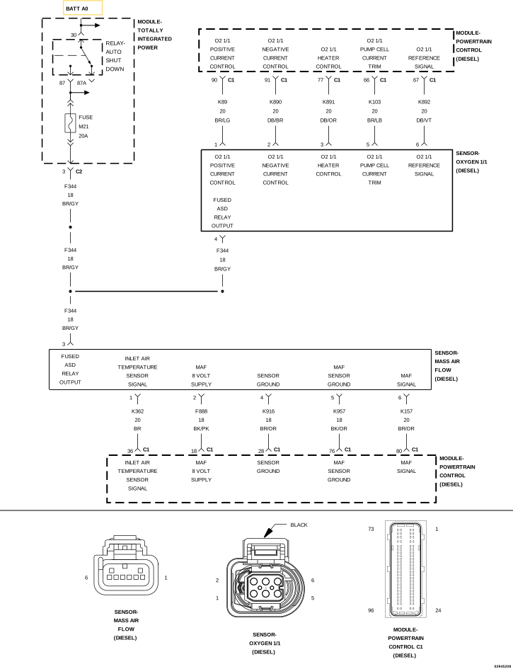 |
For a complete wiring diagram, refer to the Wiring Information.
-
When Monitored:
With the ignition on and the Oxygen Sensor in closed loop.
-
Set Condition:
The Powertrain Control Module (PCM) detects that the dynamics (amount of change between the high signal and low signal) of the O2 Sensor signal are too small.
Possible Causes |
|---|
| RESTRICTED AIR FILTER |
| RESTRICTION IN THE INTAKE SYSTEM |
| INTAKE SYSTEM LEAK |
| EXHAUST SYSTEM LEAK OR RESTRICTION |
| FUEL DELIVERY SYSTEM FAILURE |
| OXYGEN SENSOR |
| POWERTRAIN CONTROL MODULE (PCM) |
Always perform the Pre-Diagnostic Troubleshooting procedure before proceeding. (Refer to 28 - DTC-Based Diagnostics/MODULE, Powertrain Control (PCM) - Standard Procedure).
| 1. | Ignition on, engine not running. |
| 2. | With the scan tool, erase DTCs in the PCM. |
| 3. | Start the engine and allow it to reach operating temperature. |
| 4. | Test drive the vehicle. |
| 5. | With the scan tool, select View DTCs. |
Is the status Active for this DTC?
Yes
- Go To 2
No
- Perform the INTERMITTENT DTC diagnostic procedure. (Refer to 28 - DTC-Based Diagnostics/MODULE, Powertrain Control (PCM) - Standard Procedure).
| 1. | Turn the ignition off. |
| 2. | Remove and inspect the Air Filter for soiling or excessive dirt and debris which may cause air flow restriction. |
| 3. | Check the Inlet Tube for signs of dirt, snow, or ice restricting airflow into the Air Filter Box. |
Were any problems found?
Yes
- Repair or replace as necessary.
- Perform the PCM VERIFICATION TEST. (Refer to 28 - DTC-Based Diagnostics/MODULE, Powertrain Control (PCM) - Standard Procedure).
No
- Go To 3
3. CHECK FOR INTAKE SYSTEM RESTRICTIONS
| NOTE: | Damaged, restricted or poorly connected intake and Turbocharger related tubes can cause this DTC to set. |
| 1. | Turn the ignition off. |
| 2. | Inspect all air intake, crankcase vent and Turbocharger related hoses/tubes and connections. |
| 3. | Inspect the Charge Air Cooler inlet and outlet hoses/tubes and connections. |
| 4. | Inspect the EGR Air Flow Control Valve to ensure the valve is not stuck in the closed position. |
Were any problems found?
Yes
- Repair or replace as necessary.
- Perform the PCM VERIFICATION TEST. (Refer to 28 - DTC-Based Diagnostics/MODULE, Powertrain Control (PCM) - Standard Procedure).
No
- Go To 4
4. CHECK FOR INTAKE SYSTEM AIR LEAKS
| 1. | Remove the Crankcase Vent Heater. |
| 2. | Remove the Mass Air Flow Sensor from the Turbocharger Inlet Tube. |
| 3. | Seal off and/or plug the Turbocharger Inlet Tube where the MAF sensor was removed. |
| 4. | Connect the Evaporative Emissions Leak Detector Kit, EELD And Accessory 8404B to the Crankcase Vent Heater port in the intake duct and begin injecting smoke into the intake system. |
| 5. | Observe all intake system components for evidence of smoke leakage. |
Is there evidence of smoke leakage?
Yes
- Repair or replace as necessary.
- Perform the PCM VERIFICATION TEST. (Refer to 28 - DTC-Based Diagnostics/MODULE, Powertrain Control (PCM) - Standard Procedure).
No
- Go To 5
5. CHECK THE EXHAUST SYSTEM FOR LEAKS OR RESTRICTION
| 1. | Visually inspect the Exhaust system for signs of damage, leaks or restrictions. |
Were any problems found?
Yes
- Go To 6
No
- Repair or replace as necessary.
- Perform the PCM VERIFICATION TEST. (Refer to 28 - DTC-Based Diagnostics/MODULE, Powertrain Control (PCM) - Standard Procedure).
6. CHECK THE FUEL DELIVERY SYSTEM
| 1. | Perform the CHECKING THE FUEL DELIVERY SYSTEM diagnostic procedure. (Refer to 29 - Non-DTC Diagnostics/Drivability - Diesel - Diagnosis and Testing) . |
Were any problems found?
Yes
- Repair as necessary.
- Perform the PCM VERIFICATION TEST. (Refer to 28 - DTC-Based Diagnostics/MODULE, Powertrain Control (PCM) - Standard Procedure).
No
- Go To 7
| 1. | Replace the Oxygen Sensor in accordance with the service information. |
| 2. | Start the engine. |
| 3. | Allow the engine to reach normal operating temperature. |
| 4. | Test drive the vehicle. |
| 5. | With the scan tool, select View DTCs. |
Is the status Active for this DTC?
Yes
- Go To 8
No
- Test Complete.
- Perform the PCM VERIFICATION TEST. (Refer to 28 - DTC-Based Diagnostics/MODULE, Powertrain Control (PCM) - Standard Procedure).
| 1. | Using the wiring diagram/schematic as a guide, inspect the wiring and connectors between the Oxygen Sensor and the Powertrain Control Module. |
| 2. | Look for any chafed, pierced, pinched, or partially broken wires. |
| 3. | Look for broken, bent, pushed out or corroded terminals. |
| 4. | Perform any Technical Service Bulletins that may apply. |
Were any problems found?
Yes
- Repair as necessary.
- Perform the PCM VERIFICATION TEST. (Refer to 28 - DTC-Based Diagnostics/MODULE, Powertrain Control (PCM) - Standard Procedure).
No
- Replace the Powertrain Control Module in accordance with the service information.
- Perform the PCM VERIFICATION TEST. (Refer to 28 - DTC-Based Diagnostics/MODULE, Powertrain Control (PCM) - Standard Procedure).