P0268-FUEL INJECTOR 3 CIRCUIT HIGH
P0268-FUEL INJECTOR 3 CIRCUIT HIGH
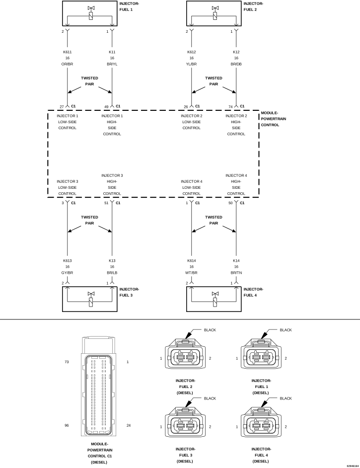 |
For a complete wiring diagram, refer to the Wiring Information.
-
When Monitored:
With the engine cranking or running.
-
Set Condition:
The Powertrain Control Module (PCM) detects a fault on a Fuel Injector Control circuit.
Possible Causes |
|---|
| FUEL INJECTOR CONTROL CIRCUITS SHORTED TO VOLTAGE |
| FUEL INJECTOR CONTROL CIRCUITS SHORTED TO GROUND |
| FUEL INJECTOR CIRCUITS SHORTED TOGETHER |
| FUEL INJECTOR CONTROL CIRCUITS OPEN/HIGH RESISTANCE |
| FUEL INJECTOR |
| POWERTRAIN CONTROL MODULE (PCM) |
Always perform the Pre-Diagnostic Troubleshooting procedure before proceeding. (Refer to 28 - DTC-Based Diagnostics/MODULE, Powertrain Control (PCM) - Standard Procedure).
| 1. | Turn the ignition on. |
| 2. | With the scan tool, erase the PCM DTCs. |
| 3. | Attempt to start the engine and test drive the vehicle. |
| 4. | With the scan tool, read the PCM DTCs. |
Did this DTC return?
Yes
- Go To 2
No
- Perform the INTERMITTENT DTC diagnostic procedure. (Refer to 28 - DTC-Based Diagnostics/MODULE, Powertrain Control (PCM) - Standard Procedure).
| NOTE: | An open ASD power supply to the PCM will cause multiple DTCs including this DTC to set. |
| NOTE: | Check the PCM for other DTCs. If other DTC's are set with this DTC refer to the symptom list and perform the CHECKING THE PCM POWER AND GROUND CIRCUITS test before continuing. |
If the PCM power and ground circuits are functioning properly continue with this test.
Yes
- Go To 3
3. CHECK THE FUEL INJECTOR CONTROL CIRCUITS FOR A SHORT TO VOLTAGE
| 1. | Turn the ignition off. |
| 2. | Disconnect all of the Fuel Injector harness connectors. |
| 3. | Disconnect the PCM C1 harness connector. |
| 4. | Remove the ASD Relay from the TIPM. |
| 5. | Connect a jumper wire between cavity 30 and cavity 87 of the ASD Relay connector. |
| 6. | Turn the ignition on. |
| 7. | Measure the voltage of each Fuel Injector High-Side Control circuit. |
| 8. | Measure the voltage of each Fuel Injector Low-Side Control circuit. |
Is the voltage above 1.0 Volt for any of the measurements?
Yes
- Repair the appropriate Fuel Injector Control circuit for a short to voltage.
- Perform the PCM VERIFICATION TEST. (Refer to 28 - DTC-Based Diagnostics/MODULE, Powertrain Control (PCM) - Standard Procedure).
No
- Go To 4
4. CHECK THE FUEL INJECTOR CONTROL CIRCUITS FOR A SHORT TO GROUND
| 1. | Turn the ignition off. |
| 2. | Remove the jumper wire and install the ASD Relay. |
| 3. | Measure the resistance between ground and each Fuel Injector High-Side Control circuits. |
| 4. | Measure the resistance between ground and each Fuel Injector Low-Side Control circuits. |
Is the resistance below 10k Ohms for any of the measurements?
Yes
- Repair the Fuel Injector Control circuit for a short to ground.
- Perform the PCM VERIFICATION TEST. (Refer to 28 - DTC-Based Diagnostics/MODULE, Powertrain Control (PCM) - Standard Procedure).
No
- Go To 5
5. FUEL INJECTOR CIRCUITS SHORTED TOGETHER
| 1. | Measure the resistance between each of the Fuel Injector High-Side Control circuits and the Fuel Injector Low-Side Control circuits. |
Is the resistance below 10k Ohms for any of the measurements?
Yes
- Repair the Fuel Injector circuits that measured below 10k Ohms for a short together.
- Perform the PCM VERIFICATION TEST. (Refer to 28 - DTC-Based Diagnostics/MODULE, Powertrain Control (PCM) - Standard Procedure).
No
- Go To 6
6. CHECK THE FUEL INJECTOR CONTROL CIRCUIT FOR AN OPEN/HIGH RESISTANCE
| 1. | Measure the resistance of each Fuel Injector High-Side and Low-Side Control circuits between its respective injector harness connector and the C1 PCM harness connector. |
Is the resistance below 5.0 Ohms for each measurement?
Yes
- Go To 7
No
- Repair the Fuel Injector Control circuit that measured above 5.0 Ohms for an open or high resistance.
- Perform the PCM VERIFICATION TEST. (Refer to 28 - DTC-Based Diagnostics/MODULE, Powertrain Control (PCM) - Standard Procedure).
7. CHECK THE FUEL INJECTOR FOR AN INTERNAL SHORT TO GROUND
| 1. | Measure the resistance between either terminal of each Fuel Injector and ground. |
Is the resistance above 10k Ohms for each measurement?
Yes
- Go To 8
No
- Replace the Fuel Injector that did not measure above 10k Ohms to ground.
- Perform the PCM VERIFICATION TEST. (Refer to 28 - DTC-Based Diagnostics/MODULE, Powertrain Control (PCM) - Standard Procedure).
8. CHECK FUEL INJECTOR RESISTANCE
| 1. | Measure the resistance of each Fuel Injector (measure across both terminals of the injector). |
Is the resistance between 150k and 210k Ohms?
Yes
- Go To 9
No
- Replace the Fuel Injector that did not measure 185k Ohms (+/- 10%)
- Perform the PCM VERIFICATION TEST. (Refer to 28 - DTC-Based Diagnostics/MODULE, Powertrain Control (PCM) - Standard Procedure).
9. MULTIPLE CYLINDER FUEL INJECTOR DTCS
Were there multiple Cylinder Fuel Injector DTCs set in the PCM?
Yes
- Go To 10
No
- Replace the Cylinder Fuel Injector 3 in accordance with the service information.
- Perform the PCM VERIFICATION TEST. (Refer to 28 - DTC-Based Diagnostics/MODULE, Powertrain Control (PCM) - Standard Procedure).
| 1. | Reconnect all harness connectors. |
| 2. | Turn the ignition on. |
| 3. | With the scan tool, clear all PCM DTCs. |
| 4. | Disconnect the Cylinder 3 Fuel Injector harness connector. |
| 5. | With the scan tool, read the PCM DTCs. |
| NOTE: | The continuing setting of multiple DTCs indicates that the disconnected injector is not the cause of these faults. |
| NOTE: | If multiple DTCs did not reset after disconnecting a single injector, replace the injector that was disconnected. In this case the lack of multiple DTCs setting indicates that the disconnected injector is the cause of these faults. |
Choose the correct result below.
The PCM set Multiple Cylinder Injector DTCs
- Reconnect the disconnected Injector harness connector and repeat test by disconnecting another injector until multiple DTCs are not set.
- Perform the PCM VERIFICATION TEST. (Refer to 28 - DTC-Based Diagnostics/MODULE, Powertrain Control (PCM) - Standard Procedure).
The PCM set only a DTC for the disconnected Cylinder Injector
- Replace the Cylinder Fuel Injector that was disconnected in accordance with the service information.
- Perform the PCM VERIFICATION TEST. (Refer to 28 - DTC-Based Diagnostics/MODULE, Powertrain Control (PCM) - Standard Procedure).