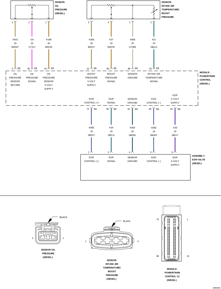
For a complete wiring diagram, refer to the Wiring Information.
Theory of Operation
The Exhaust Gas Recirculation (EGR) Valve is opened by a motor located inside the EGR Valve. The pulse width modulated motor is controlled by the Powertrain Control Module (PCM). The EGR Valve also has an internal three wire 5-Volt EGR Position Sensor. This internal sensor reports the position of the valve back to the PCM over the EGR Position Sensor Signal circuit. The EGR system and Diesel Particulate Filter regeneration will be disabled when the fault is active.
When Monitored:
With the ignition on.
Set Condition:
The Powertrain Control Module (PCM) detects that the EGR Signal circuit voltage is below 0.65 Volt for 0.5 second.
Possible Causes
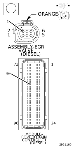
(K34) EGR POSITION SIGNAL CIRCUIT OPEN/HIGH RESISTANCE
(K34) EGR POSITION SIGNAL CIRCUIT SHORTED TO GROUND
Reconnect the EGR Valve Assembly harness connector.
2.
Reconnect the PCM C1 harness connector.
3.
Turn the ignition on.
4.
With the scan tool, erase DTCs.
5.
Turn the ignition off.
6.
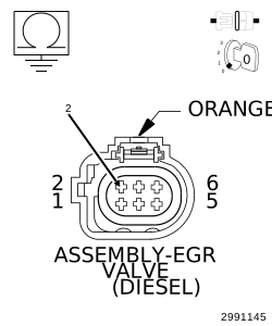
Disconnect the EGR Valve Assembly harness connector.
7.
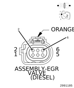
Connect a jumper between the (K34) EGR Position Signal circuit and the (K35) EGR Valve 5-Volt Supply circuit at the EGR Valve Assembly harness connector.
8.
Turn the ignition on.
9.
With the scan tool, select View DTCs.
NOTE:
The scan tool should display a P0406-EGR Position Sensor Circuit High DTC with the jumper in place.
Does the scan tool display the DTC as described above?
Yes
Replace the EGR Valve in accordance with the service information.