P083F-CLUTCH PEDAL SWITCH "A"/"B" CORRELATION
P083F-CLUTCH PEDAL SWITCH "A"/"B" CORRELATION
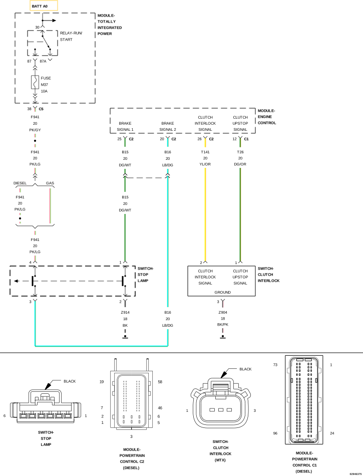 |
For a complete wiring diagram, refer to the Wiring Information.
-
When Monitored:
With the ignition on.
-
Set Condition:
The Powertrain Control Module (PCM) detects that the (T26) Clutch Upstop Switch Signal circuit signal is implausible.
Possible Causes |
|---|
| (T26) CLUTCH UPSTOP SWITCH SIGNAL CIRCUIT SHORTED TO GROUND |
| (T26) CLUTCH UPSTOP SWITCH SIGNAL CIRCUIT OPEN OR HIGH RESISTANCE |
| (Z905) GROUND CIRCUIT OPEN OR HIGH RESISTANCE |
| CLUTCH INTERLOCK SWITCH |
| POWERTRAIN CONTROL MODULE (PCM) |
Always perform the Pre-Diagnostic Troubleshooting procedure before proceeding. (Refer to 28 - DTC-Based Diagnostics/MODULE, Powertrain Control (PCM) - Standard Procedure).
| 1. | Ignition on, engine not running. |
| 2. | With the scan tool, Clear DTCs in the PCM. |
| 3. | Press and release the clutch pedal several times. |
| 4. | With the scan tool, select View DTCs. |
Is the status Active for this DTC?
Yes
- Go To 2
No
- Perform the INTERMITTENT DTC diagnostic procedure. (Refer to 28 - DTC-Based Diagnostics/MODULE, Powertrain Control (PCM) - Standard Procedure).
2. CHECK THE (T26) CLUTCH UPSTOP SWITCH SIGNAL CIRCUIT VOLTAGE
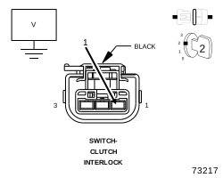 |
| 1. | Turn the ignition off. |
| 2. | Disconnect the Clutch Interlock Switch harness connector. |
| 3. | Turn the ignition on. |
| 4. | Measure the voltage of the (T26) Clutch Upstop Switch Signal circuit in the Clutch Interlock Switch harness connector. |
Is the voltage above 10.0 Volts?
Yes
- Go To 3
No
-
Go To 5
3. CHECK THE (Z905) GROUND CIRCUIT FOR AN OPEN/HIGH RESISTANCE
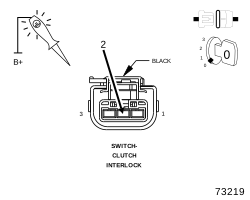 |
| 1. | Using a 12-Volt test light connected to 12 Volts, check the (Z905) Ground circuit between the Clutch Interlock Switch harness connector. |
| NOTE: | The test light should be illuminated and bright. Compare the brightness to that of a direct connection to the battery. |
Is the test light illuminated and bright?
Yes
- Go To 4
No
- Repair the (Z905) Ground for an open or high resistance.
-
Perform the PCM VERIFICATION TEST. (Refer to 28 - DTC-Based Diagnostics/MODULE, Powertrain Control (PCM)
- Standard Procedure).
4. CHECK THE CLUTCH INTERLOCK SWITCH
| 1. | Turn the ignition off. |
| 2. | Connect a jumper wire between the (Z905) Ground circuit and the (T26) Clutch Upstop Switch Signal circuit in the Clutch Interlock Switch harness connector. |
| 3. | Turn the ignition on. |
| 4. | With the scan tool, monitor the Clutch Upstop status. |
| NOTE: | The scan tool should display the Clutch Interlock status as not pressed with the jumper wire in place and pressed with the jumper wire removed. |
Does the scan tool display the status as described above?
Yes
- Replace the Clutch Interlock Switch in accordance with the service information.
- Perform the PCM VERIFICATION TEST. (Refer to 28 - DTC-Based Diagnostics/MODULE, Powertrain Control (PCM) - Standard Procedure).
No
- Go To 7
5. CHECK THE (T26) CLUTCH UPSTOP SWITCH SIGNAL CIRCUIT FOR A SHORT TO GROUND
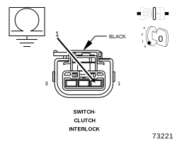 |
| 1. | Turn the ignition off. |
| 2. | Measure the resistance between ground and the (T26) Clutch Upstop Switch Signal circuit in the Clutch Interlock Switch harness connector. |
Is the resistance above 10k Ohms?
Yes
- Go To 6
No
- Repair the (T26) Clutch Upstop Switch Signal circuit for a short to ground.
-
Perform the PCM VERIFICATION TEST. (Refer to 28 - DTC-Based Diagnostics/MODULE, Powertrain Control (PCM)
- Standard Procedure).
6. CHECK THE (T26) CLUTCH UPSTOP SWITCH SIGNAL CIRCUIT FOR AN OPEN/HIGH RESISTANCE
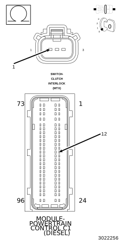 |
| 1. | Measure the resistance of the (T26) Clutch Upstop Switch Signal circuit between the Clutch Interlock Switch harness connector and the PCM C1 harness connector. |
Is the resistance below 5.0 Ohms?
Yes
- Go To 7
No
- Repair the (T26) Clutch Upstop Switch Signal for an open circuit or high resistance.
-
Perform the PCM VERIFICATION TEST. (Refer to 28 - DTC-Based Diagnostics/MODULE, Powertrain Control (PCM)
- Standard Procedure).
| 1. | Using the wiring diagram/schematic as a guide, inspect the wiring and connectors between the Clutch Interlock Switch and the Powertrain Control Module. |
| 2. | Look for any chafed, pierced, pinched, or partially broken wires. |
| 3. | Look for broken, bent, pushed out or corroded terminals. |
| 4. | Monitor the scan tool data relative to this circuit and wiggle test the wiring and connectors. |
| 5. | Look for the data to change or for the DTC to reset during the wiggle test. |
| 6. | Perform any Technical Service Bulletins that may apply. |
Were any problems found?
Yes
- Repair as necessary.
- Perform the PCM VERIFICATION TEST. (Refer to 28 - DTC-Based Diagnostics/MODULE, Powertrain Control (PCM) - Standard Procedure).
No
- Replace the Powertrain Control Module in accordance with the service information.
- Perform the PCM VERIFICATION TEST. (Refer to 28 - DTC-Based Diagnostics/MODULE, Powertrain Control (PCM) - Standard Procedure).