2012 Jeep Wrangler JK Factory Service Manual 28 - DTC-Based Diagnostics

P1649-GLOW PLUG MODULE POWER SUPPLY CIRCUIT

P1649-GLOW PLUG MODULE POWER SUPPLY CIRCUIT


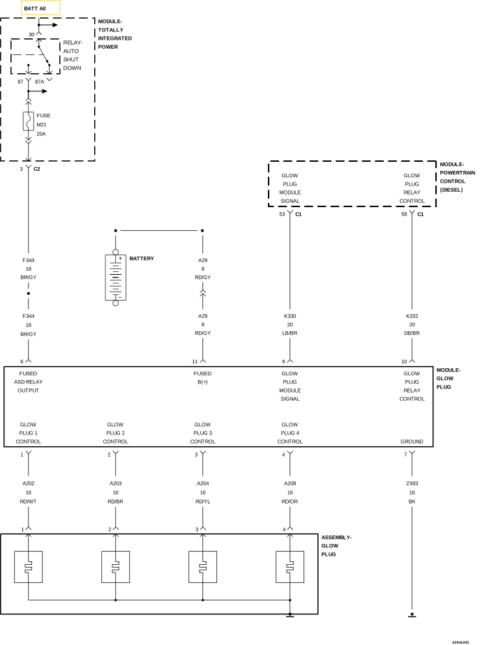
For a complete wiring diagram, refer to the Wiring Information.


Theory of Operation

The Glow Plug Module has the appearance of a large relay and is located next to the battery.The Glow Plug Module receives a signal from the Powertrain Control Module (PCM) to activate the Glow Plugs. The Glow Plug Module supplies power to the Glow Plugs and a ground path is provided through the body of the Glow Plugs. The Glow Plug Module communicates with the PCM over the (K330) Glow Plug Module Control circuit.


Possible Causes

(F344) FUSED IGNITION SWITCH OUTPUT CIRCUIT OPEN/HIGH RESISTANCE
(Z933) GLOW PLUG MODULE GROUND CIRCUIT OPEN/HIGH RESISTANCE
GLOW PLUG MODULE
POWERTRAIN CONTROL MODULE (PCM)

1. CHECK FOR ACTIVE DTC


1. Turn the ignition on.
2. With the scan tool, erase PCM DTCs.
3. Perform several engine run cycles, turning the ignition off for at least 20 seconds between each engine run cycle.
4. Turn the ignition on and wait at least 90 seconds.
5. With the scan tool, read PCM DTCs.


Did this DTC return?

Yes


No


2. CHECK THE (F344) FUSED IGNITION SWITCH OUTPUT CIRCUIT FOR AN OPEN/HIGH RESISTANCE


1. Turn the ignition off.
2. Disconnect the Glow Plug Module harness connector.
3. Turn the ignition on.
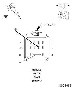
4. Using a 12-volt test light, probe the (F344) Glow Plug Module Signal circuit at the Glow Plug Module harness connector.


Is the test light illuminated and bright?

Yes


No


3. CHECK THE (Z933) GLOW PLUG MODULE GROUND CIRCUIT FOR AN OPEN/HIGH RESISTANCE


1. Turn the ignition off.
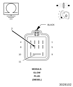
2. Measure the resistance between ground and the (Z933) Glow Plug Module Ground circuit at the Glow Plug Module harness connector.


Is the resistance below 5.0 Ohms for both measurements?

Yes


No


4. GLOW PLUG CONTROL MODULE


1. Turn the ignition off.
2. Replace the Glow Plug Module in accordance with the service information.
3. Reconnect all connectors.
4. Turn the ignition on.
5. With the scan tool, erase PCM DTCs.
6. Perform several engine run cycles, turning the ignition off for at least 20 seconds between each engine run cycle.
7. With the scan tool, read the PCM DTCs.


Did this DTC return?

Yes


No