P1C8D-POWER SUPPLY 1 CIRCUIT/OPEN
P1C8D-POWER SUPPLY 1 CIRCUIT/OPEN
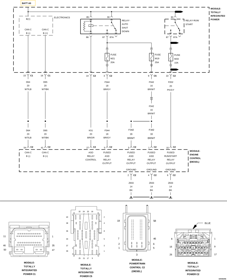 |
For a complete wiring diagram, refer to the Wiring Information.
The Powertrain Control Module (PCM) has two ASD 12 Volt supply circuits which provide power to three input circuits at the PCM C2 connector. The (F342) circuit supplies power to pins one and three. The (F344) circuit supplies power to pin five. The PCM internally monitors the voltage supply at each circuit. If the PCM sees power on one of the circuits and not the other, it performs a diagnostic check of the circuit and sets a DTC. The circuits are linked internally so that if one of the circuits is found to be open (I.E. (F342) circuit), current from the (F344) circuit will transfer over to the (F342) circuit.
-
When Monitored:
Continuously with the ignition on.
-
Set Condition:
The PCM detects an open in the (F342) Fused ASD Relay Output circuit for 1.5 seconds.
Possible Causes |
|---|
| (F342) FUSED ASD RELAY OUTPUT CIRCUIT OPEN/HIGH RESISTANCE |
| POWERTRAIN CONTROL MODULE (PCM) |
Always perform the Pre-Diagnostic Troubleshooting procedure before proceeding. (Refer to 28 - DTC-Based Diagnostics/MODULE, Powertrain Control (PCM) - Standard Procedure).
DTC IS ACTIVE
| 1. | Ignition on, engine not running. |
| 2. | With the scan tool, select View DTCs. |
Is the status Active for this DTC?
Yes
- Perform the CHECKING THE PCM POWER AND GROUNDS CIRCUITS diagnostic procedure. (Refer to 29 - Non-DTC Diagnostics/Drivability - Diesel - Diagnosis and Testing) .
No
- Perform the INTERMITTENT DTC diagnostic procedure. (Refer to 28 - DTC-Based Diagnostics/MODULE, Powertrain Control (PCM) - Standard Procedure).