P2138-ACCELERATOR PEDAL POSITION SENSOR 1/2 CORRELATION
P2138-ACCELERATOR PEDAL POSITION SENSOR 1/2 CORRELATION
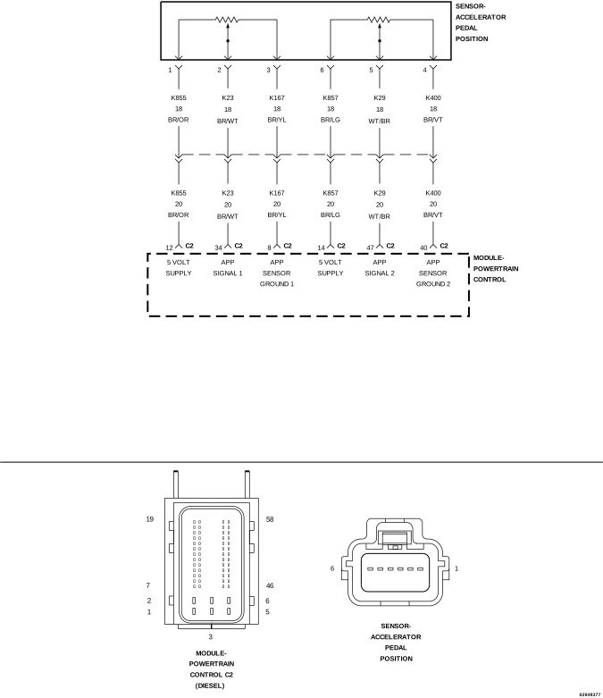 |
For a complete wiring diagram, refer to the Wiring Information.
Theory of Operation
The Accelerator Pedal Position (APP) Sensor contains two independent three wire inductive sensors. Each sensor provides independent pedal position signals to the Powertrain Control Module (PCM). The raw voltage signal from APP No.1 Sensor is two times the raw voltage signal from APP No.2 Sensor. Although the raw voltage signals differ, the scan tool converts and displays these voltages as matching percentages of pedal travel.
-
When Monitored:
With the ignition on. No other APP Sensor DTCs set. No Sensor Reference Voltage DTCs set.
-
Set Condition:
APP Sensor No.1 and APP Sensor No.2 signals do not agree for 0.4 second.
Possible Causes |
|---|
| HIGH RESISTANCE IN THE (K855) APP SENSOR NO.1 5-VOLT SUPPLY CIRCUIT |
| HIGH RESISTANCE IN THE (K23) APP SENSOR NO.1 SIGNAL CIRCUIT |
| HIGH RESISTANCE IN THE (K167) APP SENSOR NO.1 SENSOR GROUND CIRCUIT |
| HIGH RESISTANCE IN THE (K857) APP SENSOR NO.2 5-VOLT SUPPLY CIRCUIT |
| HIGH RESISTANCE IN THE (K29) APP SENSOR NO.2 SIGNAL CIRCUIT |
| HIGH RESISTANCE IN THE (K400) APP SENSOR NO.2 SENSOR GROUND CIRCUIT |
| ACCELERATOR PEDAL POSITION SENSOR |
Always perform the Pre-Diagnostic Troubleshooting procedure before proceeding. (Refer to 28 - DTC-Based Diagnostics/MODULE, Powertrain Control (PCM) - Standard Procedure).
| NOTE: | If any Sensor Reference or Sensor Supply voltage DTCs are present, perform the applicable diagnostic procedure before continuing with this test. |
| NOTE: | The APP Sensor 2 signal should always be approximately 1/2 the voltage of the APP Sensor 1 signal. |
| 1. | Ignition on, engine not running. |
| 2. | With the scan tool, clear DTCs in the PCM. |
| 3. | Fully depress and release the Accelerator Pedal several times. |
| 4. | With the scan tool, select View DTCs. |
Is the status Active for this DTC?
Yes
- Go To 2
No
- Perform the INTERMITTENT DTC diagnostic procedure. (Refer to 28 - DTC-Based Diagnostics/MODULE, Powertrain Control (PCM) - Standard Procedure).
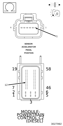
2. CHECK FOR HIGH RESISTANCE IN THE (K855) APP SENSOR NO.1 5-VOLT SUPPLY CIRCUIT
 |
| 1. | Turn the ignition off. |
| 2. | Disconnect the APP Sensor harness connector. |
| 3. | Disconnect the PCM C2 harness connector. |
| 4. | Measure the resistance of the (K855) APP Sensor No.1 5-Volt Supply circuit between the APP Sensor harness connector and the PCM C2 harness connector. |
Is the resistance below 5.0 Ohms?
Yes
- Go To 3
No
- Repair the (K855) APP Sensor No.1 5-Volt Supply circuit for an open or high resistance.
-
Perform the PCM VERIFICATION TEST. (Refer to 28 - DTC-Based Diagnostics/MODULE, Powertrain Control (PCM)
- Standard Procedure).
3. CHECK FOR HIGH RESISTANCE IN THE (K23) APP SENSOR NO.1 SIGNAL CIRCUIT
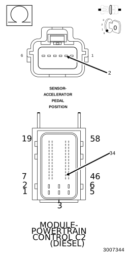 |
| 1. | Measure the resistance of the (K23) APP Sensor No.1 Signal circuit between the APP Sensor harness connector and the PCM C2 harness connector. |
Is the resistance below 5.0 Ohms?
Yes
- Go To 4
No
- Repair the (K23) APP Sensor No.1 Signal circuit for an open or high resistance.
-
Perform the PCM VERIFICATION TEST. (Refer to 28 - DTC-Based Diagnostics/MODULE, Powertrain Control (PCM)
- Standard Procedure).
4. CHECK THE (K167) APP SENSOR NO.1 GROUND CIRCUIT FOR AN OPEN/HIGH RESISTANCE
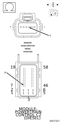 |
| 1. | Measure the resistance of the (K167) APP Sensor No.1 Signal circuit between the APP Sensor harness connector and the PCM C2 harness connector. |
Is the resistance below 5.0 Ohms?
Yes
- Go To 5
No
- Repair the (K29) APP Sensor No.1 Signal circuit for an open or high resistance.
-
Perform the PCM VERIFICATION TEST. (Refer to 28 - DTC-Based Diagnostics/MODULE, Powertrain Control (PCM)
- Standard Procedure).
5. CHECK FOR HIGH RESISTANCE IN THE (K857) APP SENSOR NO.2 5-VOLT SUPPLY CIRCUIT
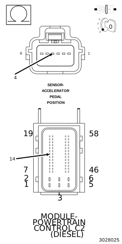 |
| 1. | Measure the resistance of the (K857) APP Sensor No.2 5-Volt Supply circuit between the APP Sensor harness connector and the PCM C2 harness connector. |
Is the resistance below 5.0 Ohms?
Yes
- Go To 6
No
- Repair the (K857) APP Sensor No.2 5-Volt Supply circuit for an open or high resistance.
- Perform the PCM VERIFICATION TEST. (Refer to 28 - DTC-Based Diagnostics/MODULE, Powertrain Control (PCM) - Standard Procedure).
6. CHECK FOR HIGH RESISTANCE IN THE (K29) APP SENSOR NO.2 SIGNAL CIRCUIT
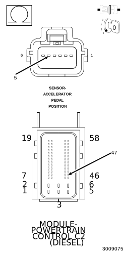 |
| 1. | Measure the resistance of the (K29) APP Sensor No.2 Signal circuit between the APP Sensor harness connector and the PCM C2 harness connector. |
Is the resistance below 5.0 Ohms?
Yes
- Go To 7
No
- Repair the (K29) APP Sensor No.2 Signal circuit for an open or high resistance.
-
Perform the PCM VERIFICATION TEST. (Refer to 28 - DTC-Based Diagnostics/MODULE, Powertrain Control (PCM)
- Standard Procedure).
7. CHECK THE (K400) APP SENSOR NO.2 GROUND CIRCUIT FOR AN OPEN/HIGH RESISTANCE
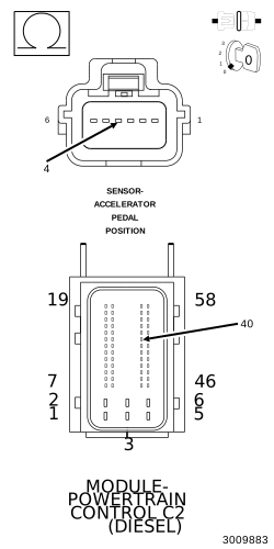 |
| 1. | Measure the resistance of the (K400) APP Sensor No. 2 Ground circuit between the APP Sensor harness connector and the PCM C2 harness connector. |
Is the resistance below 5.0 Ohms?
Yes
- Replace the Accelerator Pedal Position Sensor in accordance with the service information.
- Perform the PCM VERIFICATION TEST. (Refer to 28 - DTC-Based Diagnostics/MODULE, Powertrain Control (PCM) - Standard Procedure).
No
- Repair the (K400) APP Sensor No. 2 Ground circuit for an open or high resistance.
-
Perform the PCM VERIFICATION TEST. (Refer to 28 - DTC-Based Diagnostics/MODULE, Powertrain Control (PCM)
- Standard Procedure).