Home › 28 - DTC-Based Diagnostics › MODULE, Powertrain Control (PCM), 2.8L VM › P2231-O2 SENSOR SIGNAL CIRCUIT SHORTED TO HEATER CIRCUIT - BANK 1 SENSOR 1P2231-O2 SENSOR SIGNAL CIRCUIT SHORTED TO HEATER CIRCUIT - BANK 1 SENSOR 1
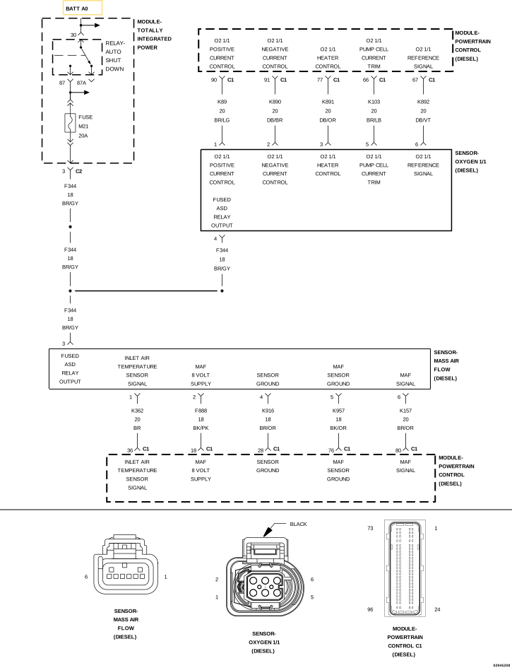
P2231-O2 SENSOR SIGNAL CIRCUIT SHORTED TO HEATER CIRCUIT - BANK 1 SENSOR 1 For a complete wiring diagram, refer to the Wiring Information .
When Monitored:
With the ignition on and the O2 Sensor 1/1 active.
Set Condition:
The Powertrain Control Module (PCM) detects that the O2 Sensor concentration level is outside of a predefined window during heater coupling detection.
Possible Causes
(K892) O2 SENSOR 1/1 SIGNAL CIRCUIT SHORTED TO THE (K891) O2 SENSOR 1/1 HEATER CONTROL CIRCUIT
OXYGEN SENSOR
POWERTRAIN CONTROL MODULE (PCM)
Always perform the Pre-Diagnostic Troubleshooting procedure before proceeding. (Refer to 28 - DTC-Based Diagnostics/MODULE, Powertrain Control (PCM)
- Standard Procedure) .
1.
DTC IS ACTIVE
2.
With the scan tool, erase DTCs in the PCM.
4.
Allow the engine to reach normal operating temperature.
5.
Test drive the vehicle and monitor the scan tool.
6.
With the scan tool, select View DTCs.
Is the status Active for this DTC? Yes
No
2.
CHECK FOR THE (K892) O2 SENSOR 1/1 SIGNAL CIRCUIT SHORTED TO THE (K891) O2 SENSOR 1/1 HEATER CONTROL CIRCUIT
1.
Turn the ignition off.
2.
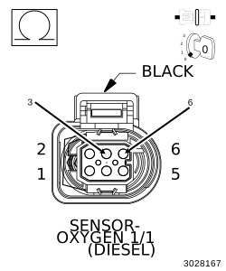
Disconnect the Oxygen Sensor harness connector.
3.
Disconnect the PCM C1 harness connector.
4.
Measure the resistance between the (K892) O2 Sensor 1/1 Signal circuit and the (K891) O2 Sensor 1/1 Heater Control circuit at the Oxygen Sensor harness connector.
Is the resistance above 10k Ohms? Yes
No
3.
OXYGEN SENSOR
1.
Turn the ignition off.
2.
Reconnect the PCM C1 harness connector.
3.
Replace the Oxygen Sensor in accordance with the service information.
5.
With the scan tool, erase DTCs in the PCM.
7.
Allow the engine to reach normal operating temperature.
8.
Test drive the vehicle and monitor the scan tool.
9.
With the scan tool, select View DTCs.
Is the status Active for this DTC? Yes
No
4.
POWERTRAIN CONTROL MODULE
1.
Using the wiring diagram/schematic as a guide, inspect the wiring and connectors between the Oxygen Sensor and the Powertrain Control Module.
2.
Look for any chafed, pierced, pinched, or partially broken wires.
3.
Look for broken, bent, pushed out or corroded terminals.
4.
Perform any Technical Service Bulletins that may apply.
Were any problems found? Yes
No