B1633-LEFT HIGH BEAM CONTROL CIRCUIT LOW
B1633-LEFT HIGH BEAM CONTROL CIRCUIT LOW
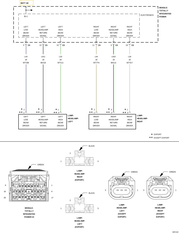 |
For a complete wiring diagram, refer to the Wiring Information.
Theory of Operation
The Totally Integrated Power Module (TIPM) receives a bus message requesting high beam lamp illumination. When this bus message is received, the TIPM provides a voltage output through the high beam driver circuit. The high beam driver circuit connects to the High Beam Lamp. A headlamp return signal circuit is used instead of a ground circuit.
-
When Monitored:
With the high beam headlamps active.
-
Set Condition:
When the Totally Integrated Power Module (TIPM) detects a low condition on the (L33) Left High Beam Driver circuit.
Possible Causes |
|---|
| (L33) LEFT HIGH BEAM DRIVER CIRCUIT SHORTED TO GROUND |
| (L33) LEFT HIGH BEAM DRIVER CIRCUIT SHORTED TO THE (L911) LEFT HEADLAMP RETURN SIGNAL CIRCUIT |
| LEFT HIGH BEAM BULB |
| TOTALLY INTEGRATED POWER MODULE (TIPM) |
| 1. | Turn the ignition on. |
| 2. | With the scan tool, clear all DTCs. |
| 3. | Turn the High Beam Headlamps on. |
| 4. | With the scan tool, read DTCs. |
Does the scan tool display DTC: B1633-LEFT HI BEAM CONTROL CIRCUIT LOW?
Yes
- Go To 2
No
- Test complete, the condition or conditions that originally set this DTC are not present at this time. Using the wiring diagrams as a guide, check all related splices and connectors for signs of water intrusion, corrosion, pushed out or bent terminals, and correct pin tension.
- Perform the BODY VERIFICATION TEST. (Refer to 28 - DTC-Based Diagnostics/MODULE, Totally Integrated Power (TIPM) - Standard Procedure).
2. ATTEMPT TO SET THE OPPOSITE DTC
| 1. | Turn the ignition off. |
| 2. | Disconnect the Left Headlamp Lamp harness connector. |
| 3. | Turn the ignition on. |
| 4. | With the scan tool, read DTCs. |
Does the scan tool display DTC: B1634-LEFT HI BEAM CONTROL CIRCUIT HIGH?
Yes
- Replace the Left High Beam Bulb in accordance with the Service Information.
- Perform the BODY VERIFICATION TEST. (Refer to 28 - DTC-Based Diagnostics/MODULE, Totally Integrated Power (TIPM) - Standard Procedure).
No
- Go To 3
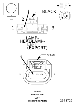
3. CHECK THE (L33) LEFT HIGH BEAM DRIVER CIRCUIT FOR A SHORT TO GROUND
 |
| 1. | Turn the ignition off. |
| 2. | Disconnect the TIPM C3 harness connector. |
| 3. | Measure the resistance between ground and the (L33) Left High Beam Driver circuit. |
Is the resistance above 10k Ohms?
Yes
- Go To 4
No
- Repair the short to ground in the (L33) Left High Beam Driver circuit.
-
Perform the BODY VERIFICATION TEST. (Refer to 28 - DTC-Based Diagnostics/MODULE, Totally Integrated Power (TIPM)
- Standard Procedure).
4. CHECK THE (L33) LEFT HIGH BEAM DRIVER CIRCUIT FOR A SHORT TO THE (L911) LEFT HEADLAMP RETURN SIGNAL CIRCUIT
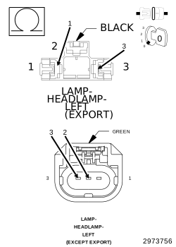 |
| 1. | Measure the resistance between the (L33) Left High Beam Driver circuit and the (L911) Left Headlamp Return Signal circuit. |
Is the resistance above 10k Ohms?
Yes
- Replace the Totally Integrated Power Module (TIPM) in accordance with the Service Information.
- Perform the BODY VERIFICATION TEST. (Refer to 28 - DTC-Based Diagnostics/MODULE, Totally Integrated Power (TIPM) - Standard Procedure).
No
- Repair the short between the (L33) Left High Beam Driver circuit and the (L911) Left Headlamp Return Signal circuit.
-
Perform the BODY VERIFICATION TEST. (Refer to 28 - DTC-Based Diagnostics/MODULE, Totally Integrated Power (TIPM)
- Standard Procedure).