2012 Jeep Wrangler JK Factory Service Manual 28 - DTC-Based Diagnostics

C141E-REAR DIFFERENTIAL CONTROL CIRCUIT HIGH

C141E-REAR DIFFERENTIAL CONTROL CIRCUIT HIGH


For a complete wiring diagram Refer to the Wiring Information.


Possible Causes

(G305) REAR LOCKER RELAY CONTROL CIRCUIT SHORTED TO VOLTAGE
REAR LOCKER (OFF-ROAD) RELAY
REAR LOCKER SOLENOID
TOTALLY INTEGRATED CONTROL MODULE (TIPM)

1. ACTIVE DTC


1. Ignition on, engine not running.
2. With the scan tool, read DTCs.


Is the DTC active at this time?

Yes


No


2. REAR LOCKER SOLENOID OPERATION


NOTE: Before continuing with the below diagnostic test, ensure the TIPM harness connector seal is installed correctly. Inspect the terminals on both harness connector and the module for damage. Failure to do so can result in misdiagnoses of the system.
1. Turn the ignition off.
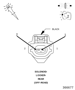
2. Disconnect the Rear Locker Solenoid harness connector.
3. Ignition on, engine not running.
4. Using a 12-volt test light, jump across from the (T526) Rear Locker Relay Output circuit and the (Z905) Ground circuit in the Rear Locker harness connector.
5. With a scan tool, actuate the Rear Locker Solenoid.


Does the test light flash on and off?

Yes


No


3. REAR LOCKER (OFF ROAD) RELAY


1. Turn the ignition off.
2. Verify the Rear Locker (OFF-ROAD) Relay is installed properly and that the terminals are making a tight fit.
3. Remove the Rear Locker (OFF-ROAD) Relay and substitute it with a known good Relay.
4. Ignition on, engine not running.
5. Using a 12-volt test light, jump across from the (T526) Rear Locker Relay Output circuit and the (Z905) Ground circuit in the Rear Locker harness connector.
6. With the scan tool, actuate the Rear Locker Solenoid.


Does the test light illuminate and flash on and off?

Yes


No


4. (G305) REAR LOCKER RELAY CONTROL CIRCUIT SHORTED TO VOLTAGE


1. Turn the ignition off.
2. Disconnect the C2 TIPM harness connector.
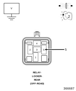
3. Remove the Rear Locker (OFF-ROAD) Relay.
4. Ignition on, engine not running.
5. Measure the voltage on the (G305) Rear Locker Relay Control circuit at the relay connection.


Is there any voltage present?

Yes


No


5. TOTALLY INTEGRATED POWER MODULE (TIPM)


NOTE: Before continuing, check the TIPM harness connector terminals for corrosion, damage, or terminal push out. Repair as necessary.
1. Using the schematics as a guide, inspect the wire harness and connectors. Pay particular attention to all Power and Ground circuits.


Were there any problems found?

Yes


No


6. INTERMITTENT WIRING AND CONNECTORS


1. The conditions necessary to set this DTC are not present at this time.
2. Using the schematics as a guide, inspect the wiring and connectors specific to this circuit.
3. Wiggle test the wiring harness and connectors while checking for shorted and open circuits.
4. Using the scan tool, monitor the data related to this circuit while performing the wiggle test. Look for the data to change or for the DTC to reset.


Were there any problems found?

Yes


No