For a complete wiring diagram, refer to the Wiring Information.
When Monitored:
Ignition on
Battery voltage above 10.4 volts
Set Condition:
The fuel level sensor signal voltage goes above the maximum acceptable value. One Trip Fault. Three good trips to turn off the MIL.
Possible Causes
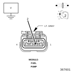
(N4) FUEL LEVEL SENSOR SIGNAL CIRCUIT SHORTED TO VOLTAGE
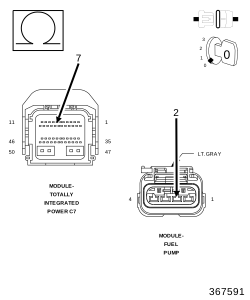
(N4) FUEL LEVEL SENSOR SIGNAL CIRCUIT OPEN
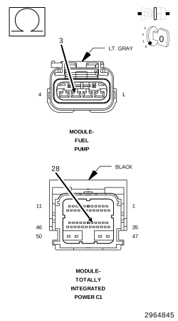
(K91) SENSOR GROUND CIRCUIT OPEN
FUEL LEVEL SENSOR
TOTALLY INTEGRATED POWER MODULE (TIPM)
1.
ACTIVE DTC
NOTE:
Diagnose any CAN Communication DTCs before continuing.
1.
Start the engine.
2.
Allow the engine to reach normal operating temperature.
3.
With a scan tool, read DTCs and record the related Freeze Frame data.
NOTE:
It may be necessary to drive the vehicle to meet the conditions to set this DTC, try to repeat the conditions in which the fault originally set by reviewing the Freeze Frame data.
Test complete, the condition or conditions that originally set this DTC are not present at this time. Using the wiring diagrams as a guide, check all related splices and connectors for signs of water intrusion, corrosion, pushed out or bent terminals, and correct pin tension.
2.
CHECK THE FUEL LEVEL SENSOR
1.
Turn the ignition off.
2.
Disconnect the Fuel Pump Module electrical harness connector.
3.
Ignition on, engine not running.
4.
With a scan tool, monitor the Fuel Level Signal voltage.
5.
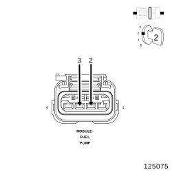
Connect a jumper wire between the (N4) Fuel Level Sensor Signal circuit and the (K91) Sensor ground circuit.
Did the Fuel Level voltage change from approximately 5 volts to 0 volts?
Yes
Verify that there is good pin to terminal contact at the Fuel Pump Module, and the Totally Integrated Power Module connectors. If OK, replace the Fuel Level Sensor/Fuel Pump Module.
Using the wiring diagram/schematic as a guide, inspect the wiring and connectors between the Fuel Pump Module and the Totally Integrated Power Module (TIPM).
2.
Look for any chafed, pierced, pinched, or partially broken wires.
3.
Look for broken, bent, pushed out or corroded terminals. Verify that there is good pin to terminal contact in the Fuel Pump Module and the TIPM connectors.
4.
Perform any Technical Service Bulletins that may apply.