P129C-INVERTER CONTROL CIRCUIT HIGH
P129C-INVERTER CONTROL CIRCUIT HIGH
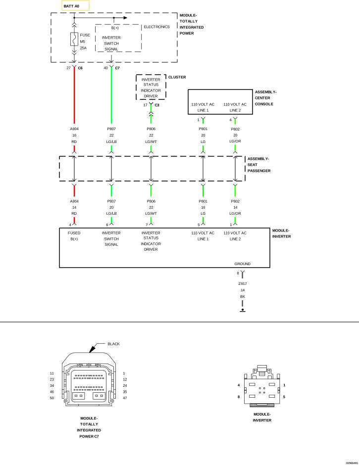 |
For a complete wiring diagram, refer to the Wiring Information.
Theory of Operation
Once the 115 Volt AC Outlet switch is pressed, the Switch Bank Module sends a message over the Local Interface Network (LIN) to the Cluster (CCN) indicating the switch has been pressed. The Cluster (CCN) then sends a message over the Controller Area Network (CAN) bus to the Totally Integrated Power Module (TIPM) to enable the Power Inverter Module. The TIPM provides a voltage output to enable the Power Inverter Module. Once the Power Inverter Module is functional, it sends a signal to the Cluster (CCN) indicating that it is ready to function. The Cluster (CCN) then requests the Switch Bank Module to illuminate the status indicator on the 115 Volt AC Outlet switch.
-
When Monitored:
With the ignition on.
Battery voltage greater than 10 volts.
Inverter commanded on.
-
Set Condition:
If the TIPM detects an open or short high condition on the (P807) Inverter Switch Signal circuit.
Possible Causes |
|---|
| (P807) INVERTER SWITCH SIGNAL CIRCUIT SHORTED TO VOLTAGE |
| (P807) INVERTER SWITCH SIGNAL CIRCUIT OPEN |
| POWER INVERTER MODULE |
| TOTALLY INTEGRATED POWER MODULE (TIPM) |
1. TEST FOR INTERMITTENT CONDITION
| 1. | Turn the ignition on. |
| 2. | With the scan tool, record and erase DTCs. |
| 3. | Operate the 115 Volt AC Outlet switch several times. |
| 4. | With the scan tool, read DTCs. |
Is the DTC active at this time?
Yes
- Go To 2
No
- Test complete, the condition or conditions that originally set this DTC are not present at this time. Using the wiring diagrams as a guide, check all related splices and connectors for signs of water intrusion, corrosion, pushed out or bent terminals, and correct pin tension.
- Perform the BODY VERIFICATION TEST. (Refer to 28 - DTC-Based Diagnostics/MODULE, Totally Integrated Power (TIPM) - Standard Procedure).
2. CHECK (P807) INVERTER SWITCH SIGNAL CIRCUIT FOR A SHORT TO VOLTAGE
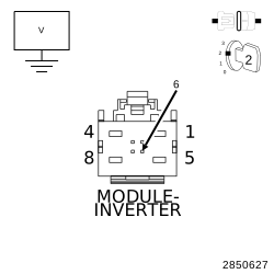 |
| 1. | Turn the ignition off. |
| 2. | Disconnect the Inverter Module harness connector. |
| 3. | Disconnect the TIPM C7 harness connector. |
| 4. | Turn the ignition on. |
| 5. | Measure the voltage between ground and the (P807) Inverter Switch Signal circuit at the Inverter Module harness connector. |
Is there any voltage present?
Yes
- Repair the short to voltage in the (P807) Inverter Switch Signal circuit.
- Perform the BODY VERIFICATION TEST. (Refer to 28 - DTC-Based Diagnostics/MODULE, Totally Integrated Power (TIPM) - Standard Procedure).
No
-
Go To 3
3. CHECK (P807) INVERTER SWITCH SIGNAL CIRCUIT FUNCTION
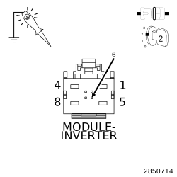 |
| 1. | Turn the ignition off. |
| 2. | Reconnect the TIPM C7 harness connector. |
| 3. | Turn the ignition on. |
| 4. | Using a 12-volt test light connected to ground, check the (P807) Inverter Switch Signal circuit at the Inverter Module harness connector. |
| 5. | With the scan tool, actuate the Inverter Switch. |
| NOTE: | The test light should be illuminated and brightly. Compare the brightness to that of a direct connection to the battery. |
Does the test light illuminate brightly?
Yes
- Replace the Power Inverter Module in accordance with the Service Information.
- Perform the BODY VERIFICATION TEST. (Refer to 28 - DTC-Based Diagnostics/MODULE, Totally Integrated Power (TIPM) - Standard Procedure).
No
-
Go To 4
4. CHECK THE (P807) INVERTER SWITCH SIGNAL CIRCUIT FOR AN OPEN
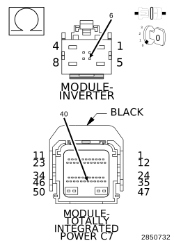 |
| 1. | Turn the ignition off. |
| 2. | Disconnect the TIPM C7 harness connector. |
| 3. | Measure the resistance of the (P807) Inverter Switch Signal circuit between the TIPM C7 harness connector and the Inverter Module harness connector. |
Is the resistance below 5.0 Ohms?
Yes
- Replace the TIPM in accordance with the Service Information.
- Perform the BODY VERIFICATION TEST. (Refer to 28 - DTC-Based Diagnostics/MODULE, Totally Integrated Power (TIPM) - Standard Procedure).
No
- Repair the open in the (P807) Inverter Switch Signal circuit.
-
Perform the BODY VERIFICATION TEST. (Refer to 28 - DTC-Based Diagnostics/MODULE, Totally Integrated Power (TIPM)
- Standard Procedure).