B161B-COURTESY/DOME LAMP CONTROL CIRCUIT LOW
For a complete wiring diagram, refer to the Wiring Information.
-
When Monitored:
Continuously
-
Set Condition:
When the Cluster detects a short to ground on the Control circuit.
Possible Causes |
|---|
| (M24) COURTESY LAMPS DRIVER CIRCUIT SHORTED TO GROUND |
| CLUSTER |
| 1. | Turn the ignition on. |
| 2. | Turn the Courtesy Lamps on. |
| 3. | With the scan tool, read DTCs. |
Does the scan display this DTC as active?
Yes
- Go To 2
No
- Test complete, the condition or conditions that originally set this DTC are not present at this time. Using the wiring diagrams as a guide, check all related splices and connectors for signs of water intrusion, corrosion, pushed out or bent terminals, and correct pin tension.
- Perform the BODY VERIFICATION TEST. (Refer to 28 - DTC-Based Diagnostics/MODULE, Totally Integrated Power (TIPM) - Standard Procedure).
2. CHECK THE (M24) COURTESY LAMPS DRIVER CIRCUIT FOR A SHORT TO GROUND
| NOTE: | Inspect the Dome Lamps. Repair or replace if damaged. |
| NOTE: | Perform this test procedure with all Lamp harness connectors disconnected. |
| 1. | Turn the ignition off. |
| 2. | Disconnect the Dome Lamp harness connectors. |
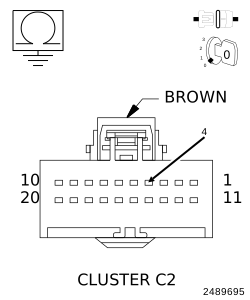
| 3. | Disconnect the Cluster C2 harness connector. |
| 4. | Measure the resistance between ground and the (M24) Courtesy Lamp Driver circuit. |
Is the resistance below 5.0 Ohms?
Yes
- Repair the (M24) Courtesy Lamp Driver circuit for a short to ground.
- Perform the BODY VERIFICATION TEST. (Refer to 28 - DTC-Based Diagnostics/MODULE, Totally Integrated Power (TIPM) - Standard Procedure).
No
- Replace the Cluster in accordance with the Service Information.
-
Perform the BODY VERIFICATION TEST. (Refer to 28 - DTC-Based Diagnostics/MODULE, Totally Integrated Power (TIPM)
- Standard Procedure).