Home › 28 - DTC-Based Diagnostics › NODE, Cabin Compartment (CCN) › U0161-LOST COMMUNICATION WITH COMPASS MODULEU0161-LOST COMMUNICATION WITH COMPASS MODULE
U0161-LOST COMMUNICATION WITH COMPASS MODULE For a complete wiring diagram, refer to the Wiring Information .
Possible Causes
(D506) LIN BUS CIRCUIT OPEN
(F921) FUSED IGNITION SWITCH OUTPUT (RUN) CIRCUIT OPEN
(Z916) GROUND CIRCUIT OPEN
COMPASS MODULE
INSTRUMENT CLUSTER
1.
CHECK FOR AN ACTIVE DTC
NOTE:
Remove any electronic devices (laptop computers, cell phones) from
the instrument panel.
NOTE:
Before proceeding, check the compass variance and calibration in
accordance with the Service Information.
2.
With the scan tool,
record and erase DTCs.
4.
With the scan tool,
read DTCs.
Does
the scan tool display this DTC as active? Yes
No
2.
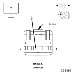
(D506) LIN BUS CIRCUIT
1.
Turn the ignition
off.
2.
Disconnect the
Compass Module harness connector.
4.
Measure the voltage
of the (D506) LIN BUS circuit.
Is the
voltage above 5 volts? Yes
No
3.
(D506) LIN BUS CIRCUIT OPEN
1.
Turn the ignition
off.
2.
Disconnect the
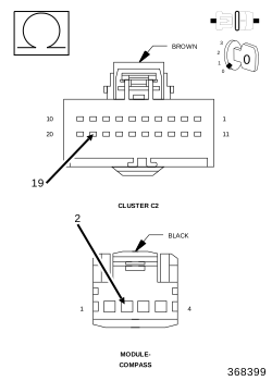
Instrument Cluster C2 harness connector.
3.
Measure the resistance
of the (D506) LIN BUS circuit.
Is the
resistance below 10K ohms? Yes
No
4.
(F921) FUSED IGNITION SWITCH OUTPUT (RUN) CIRCUIT OPEN
2.
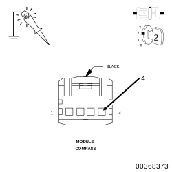
Using a 12-volt
test light connected to ground, check the (F921) Fused Ignition Switch
Output (RUN) circuit at the Compass Module harness connector.
Does
the test light illuminate brightly? Yes
No
5.
(Z916) GROUND CIRCUIT OPEN
1.
Turn the ignition
off.
2.
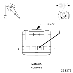
Using a 12-volt
test light connected to 12-volts, check the (Z916) Ground circuit
at the Compass Module harness connector.
Does
the test light illuminate brightly? Yes
No