Power Doors
DRIVER DOOR LOCK INOPERATIVE
DRIVER DOOR LOCK INOPERATIVE
 |
For a complete wiring diagram, refer to the Wiring Information.
Possible Causes |
|---|
| (P930) DRIVER DOOR LOCK DRIVER CIRCUIT OPEN |
| (P930) DRIVER DOOR LOCK DRIVER CIRCUIT SHORT TO GROUND |
| (P910) DRIVER DOOR UNLOCK DRIVER CIRCUIT OPEN |
| (P910) DRIVER DOOR UNLOCK DRIVER CIRCUIT SHORT TO GROUND |
| DRIVER DOOR LATCH |
| TOTALLY INTEGRATED POWER MODULE (TIPM) |
1. DRIVER DOOR LATCH INOPERATIVE
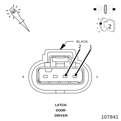 |
| 1. | Disconnect the Driver Door Latch connector. |
| 2. | Connect a test light between the (P930) Driver Door Lock Driver circuit and the (P910) Driver Door Unlock Driver circuit. |
| 3. | Close the front doors or trip the door latches to the closed position. |
| 4. | Operate the door locks in both positions and observe the test light. |
Does the test light illuminate brightly for approximately 300 ms. when the door locks are actuated?
Yes
- Replace the Driver Door Latch.
- Perform the BODY VERIFICATION TEST. (Refer to 28 - DTC-Based Diagnostics/MODULE, Totally Integrated Power (TIPM) - Standard Procedure).
No
-
Go To 2
2. CHECK (P910) DRIVER DOOR UNLOCK DRIVER CIRCUIT OPEN
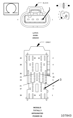 |
| 1. | Turn the ignition off. |
| 2. | Disconnect the TIPM C6 connector. |
| 3. | Measure the resistance of the (P910) Driver Door Unlock Driver circuit between the Latch connector and the TIPM C6 connector. |
Is the resistance below 2.0 ohms?
No
- Using the wiring diagram/schematic as a guide, measure the circuit from the in-line door harness connector to the latch connector to determine if the wire is open in the door harness or the instrument panel harness. Repair the (P910) Driver Door Unlock Driver circuit for an open.
- Perform the BODY VERIFICATION TEST. (Refer to 28 - DTC-Based Diagnostics/MODULE, Totally Integrated Power (TIPM) - Standard Procedure).
Yes
-
Go To 3
3. CHECK (P910) DRIVER DOOR UNLOCK DRIVER CIRCUIT SHORT TO GROUND
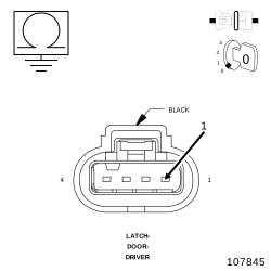 |
| 1. | Measure the resistance between Ground and the (P910) Driver Door Unlock Driver circuit. |
Is the resistance below 1,000 ohms?
Yes
- Using the wiring diagram/schematic as a guide, measure the circuit from the in-line door harness connector to ground to determine if the wire is shorted in the door harness or the instrument panel harness. Repair the (P910) Driver Door Unlock Driver circuit for a short to ground.
- Perform the BODY VERIFICATION TEST. (Refer to 28 - DTC-Based Diagnostics/MODULE, Totally Integrated Power (TIPM) - Standard Procedure).
No
-
Go To 4
4. CHECK (P930) DRIVER DOOR LOCK DRIVER CIRCUIT OPEN
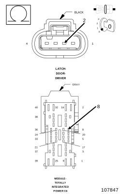 |
| 1. | Measure the resistance of the (P930) Driver Door Lock Driver circuit between the TIPM C6 connector and the Driver Door Latch connector. |
Is the resistance below 2.0 ohms?
Yes
- Go To 5
No
- Using the wiring diagram/schematic as a guide, measure the circuit from the in-line door harness connector to the latch connector to determine if the wire is open in the door harness or the instrument panel harness. Repair the (P930) Driver Door Lock Driver circuit for an open.
-
Perform the
BODY VERIFICATION TEST. (Refer
to 28 - DTC-Based Diagnostics/MODULE, Totally Integrated Power (TIPM)
- Standard Procedure).
5. CHECK (P930) DRIVER DOOR LOCK DRIVER CIRCUIT SHORT TO GROUND
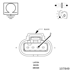 |
| 1. | Measure the resistance between Ground and the (P930) Driver Door Lock Driver circuit. |
Is the resistance below 1,000 ohms?
Yes
- Using the wiring diagram/schematic as a guide, measure the circuit from the in-line door harness connector to ground to determine if the wire is shorted in the door harness or the instrument panel harness. Repair the (P930) Driver Door Lock Driver circuit for a short to ground.
- Perform the BODY VERIFICATION TEST. (Refer to 28 - DTC-Based Diagnostics/MODULE, Totally Integrated Power (TIPM) - Standard Procedure).
No
- Replace the Totally Integrated Power Module in accordance with the Service Information.
-
Perform the
BODY VERIFICATION TEST. (Refer
to 28 - DTC-Based Diagnostics/MODULE, Totally Integrated Power (TIPM)
- Standard Procedure).
ONE PASSENGER DOOR LOCK INOPERATIVE
ONE PASSENGER DOOR LOCK INOPERATIVE
 |
For a complete wiring diagram, refer to the Wiring Information.
Possible Causes |
|---|
| (P32), (P38) OR (P920) DOOR LOCK DRIVER CIRCUIT OPEN |
| (P32, (P38) OR (P920) DOOR LOCK DRIVER CIRCUIT SHORT TO GROUND |
| (P5), (P34) OR (P940) DOOR UNLOCK DRIVER CIRCUIT OPEN |
| (P5), (P34) OR (P940) DOOR UNLOCK DRIVER CIRCUIT SHORT TO GROUND |
| TOTALLY INTEGRATED POWER MODULE (TIPM) |
| DOOR LATCH |
1. PASSENGER DOOR LATCH INOPERATIVE
| NOTE: | Graphics in this test show Left Rear Latch but the other 2 passenger latches are similar. |
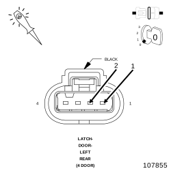 |
| 1. | Turn the ignition off. |
| 2. | Disconnect the inoperative Passenger Door latch connector. |
| 3. | Connect a test light between the Door Lock Driver circuit and the Door Unlock Driver circuit. |
| 4. | Close the front doors or trip the door latches to the closed position. |
| 5. | Operate the door locks in both positions and observe the test light. |
Does the test light illuminate brightly for approximately 300 ms. when the door locks are actuated?
Yes
- Replace the Passenger Door Latch Assembly.
- Perform the BODY VERIFICATION TEST. (Refer to 28 - DTC-Based Diagnostics/MODULE, Totally Integrated Power (TIPM) - Standard Procedure).
No
-
Go To 2
2. PASSENGER DOOR UNLOCK DRIVER CIRCUIT OPEN
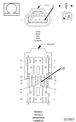 |
| 1. | Turn the ignition off. |
| 2. | Disconnect the TIPM C5 connector. |
| 3. | Measure the resistance of the appropriate Door Unlock Driver circuit between the Latch connector and the TIPM C5 connector. |
Is the resistance below 2.0 ohms?
No
- Using the wiring diagram/schematic as a guide, measure the circuit from the in-line door harness connector to the latch connector to determine if the wire is open in the door harness or the instrument panel harness. Repair the appropriate Door Unlock Driver circuit for an open.
- Perform the BODY VERIFICATION TEST. (Refer to 28 - DTC-Based Diagnostics/MODULE, Totally Integrated Power (TIPM) - Standard Procedure).
Yes
-
Go To 3
3. PASSENGER DOOR UNLOCK DRIVER CIRCUIT SHORT TO GROUND
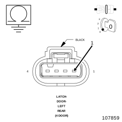 |
| 1. | Measure the resistance between Ground and the appropriate Door Unlock Driver circuit. |
Is the resistance below 1,000 ohms?
Yes
- Using the wiring diagram/schematic as a guide, measure the circuit from the in-line door harness connector to ground to determine if the wire is shorted in the door harness or the instrument panel harness. Repair the appropriate Door Unlock Driver circuit for a short to ground.
- Perform the BODY VERIFICATION TEST. (Refer to 28 - DTC-Based Diagnostics/MODULE, Totally Integrated Power (TIPM) - Standard Procedure).
No
-
Go To 4
4. PASSENGER DOOR LOCK DRIVER CIRCUIT OPEN
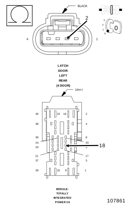 |
| 1. | Disconnect the TIPM C6 connector. |
| 2. | Measure the resistance of the appropriate Door Lock Driver circuit between the TIPM C6 connector and the appropriate Door Latch connector. |
Is the resistance below 2.0 ohms?
Yes
- Go To 5
No
- Using the wiring diagram/schematic as a guide, measure the circuit from the in-line door harness connector to the latch connector to determine if the wire is open in the door harness or the instrument panel harness. Repair the appropriate Door Lock Driver circuit for an open.
-
Perform the
BODY VERIFICATION TEST. (Refer
to 28 - DTC-Based Diagnostics/MODULE, Totally Integrated Power (TIPM)
- Standard Procedure).
5. PASSENGER DOOR LOCK DRIVER CIRCUIT SHORT TO GROUND
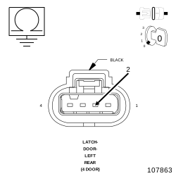 |
| 1. | Measure the resistance between Ground and the appropriate Door Lock Driver circuit. |
Is the resistance below 1,000 ohms?
Yes
- Using the wiring diagram/schematic as a guide, measure the circuit from the in-line door harness connector to ground to determine if the wire is shorted in the door harness or the instrument panel harness. Repair the appropriate Door Lock Driver circuit for a short to ground.
- Perform the BODY VERIFICATION TEST. (Refer to 28 - DTC-Based Diagnostics/MODULE, Totally Integrated Power (TIPM) - Standard Procedure).
No
- Replace the Totally Integrated Power Module (TIPM) in accordance with the Service Information.
-
Perform the
BODY VERIFICATION TEST. (Refer
to 28 - DTC-Based Diagnostics/MODULE, Totally Integrated Power (TIPM)
- Standard Procedure).
SWING GATE LOCK INOPERATIVE
SWING GATE LOCK INOPERATIVE
 |
For a complete wiring diagram, refer to the Wiring Information.
Possible Causes |
|---|
| (P304) SWIING GATE LOCK DRIVER CIRCUIT OPEN |
| (P304) SWING GATE LOCK DRIVER CIRCUIT SHORT TO GROUND |
| (P306) SWING GATE UNLOCK DRIVER CIRCUIT OPEN |
| (P306) SWING GATE UNLOCK DRIVER CIRCUIT SHORT TO GROUND |
| SWING GATE LATCH |
| TOTALLY INTEGRATED POWER MODULE (TIPM) |
1. SWING GATE LATCH INOPERATIVE
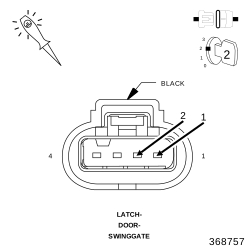 |
| 1. | Disconnect the Swing Gate Latch connector. |
| 2. | Connect a test light between the (P304) Swing Gate Lock Driver circuit and the (P406) Swing Gate Unlock Driver circuit. |
| 3. | Close the front doors or trip the front door latches to the closed position. |
| 4. | Operate the door locks in both positions and observe the test light. |
Does the test light illuminate brightly for approximately 300 ms. when the door locks are actuated?
Yes
- Replace the Swing Gate Latch.
- Perform the BODY VERIFICATION TEST. (Refer to 28 - DTC-Based Diagnostics/MODULE, Totally Integrated Power (TIPM) - Standard Procedure).
No
-
Go To 2
2. (P306) SWING GATE UNLOCK DRIVER CIRCUIT OPEN
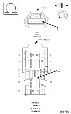 |
| 1. | Turn the ignition off. |
| 2. | Disconnect the TIPM C5 connector. |
| 3. | Measure the resistance of the (P306) Swing Gate Unlock Driver circuit between the Latch connector and the TIPM C5 connector. |
Is the resistance below 2.0 ohms?
No
- Repair the (P306) Swing Gate Unlock Driver circuit for an open.
- Perform the BODY VERIFICATION TEST. (Refer to 28 - DTC-Based Diagnostics/MODULE, Totally Integrated Power (TIPM) - Standard Procedure).
Yes
-
Go To 3
3. (P306) SWING GATE UNLOCK DRIVER CIRCUIT SHORT TO GROUND
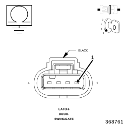 |
| 1. | Measure the resistance between Ground and the (P306) Swing Gate Unlock Driver circuit. |
Is the resistance below 1,000 ohms?
Yes
- Repair the (P306) Swing Gate Unlock Driver circuit for a short to ground.
- Perform the BODY VERIFICATION TEST. (Refer to 28 - DTC-Based Diagnostics/MODULE, Totally Integrated Power (TIPM) - Standard Procedure).
No
-
Go To 4
4. (P304) SWING GATE LOCK DRIVER CIRCUIT OPEN
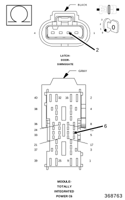 |
| 1. | Disconnect the TIPM C6 connector. |
| 2. | Measure the resistance of the (P304) Swing Gate Lock Driver circuit between the TIPM C6 connector and the Swing Gate Latch connector. |
Is the resistance below 2.0 ohms?
Yes
- Go To 5
No
- Repair the (P304) Swing Gate Lock Driver circuit for an open.
-
Perform the
BODY VERIFICATION TEST. (Refer
to 28 - DTC-Based Diagnostics/MODULE, Totally Integrated Power (TIPM)
- Standard Procedure).
5. (P304) SWING GATE DOOR LOCK DRIVER CIRCUIT SHORT TO GROUND
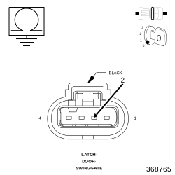 |
| 1. | Measure the resistance between Ground and the (P304) Swing Gate Lock Driver circuit. |
Is the resistance below 1,000 ohms?
Yes
- Repair the (P304) Swing Gate Lock Driver circuit for a short to ground.
- Perform the BODY VERIFICATION TEST. (Refer to 28 - DTC-Based Diagnostics/MODULE, Totally Integrated Power (TIPM) - Standard Procedure).
No
- Replace the Totally Integrated Power Module in accordance with the Service Information.
-
Perform the
BODY VERIFICATION TEST. (Refer
to 28 - DTC-Based Diagnostics/MODULE, Totally Integrated Power (TIPM)
- Standard Procedure).