COMPONENTS, Radio Noise Suppression
DESCRIPTION
DESCRIPTION
Radio Frequency Interference (RFI) and ElectroMagnetic Interference (EMI) noise suppression is accomplished primarily through circuitry internal to the radio receivers. These internal suppression devices are only serviced as part of the radio receiver.
External suppression devices that are used on this vehicle to control RFI or EMI noise include the following:
DIAGNOSIS AND TESTING - RADIO NOISE SUPPRESSION COMPONENTS
DIAGNOSIS AND TESTING - RADIO NOISE SUPPRESSION COMPONENTS
On vehicles equipped with airbags, (refer to electrical/restraints) before attempting any steering wheel, steering column, or instrument panel component diagnosis or service. Failure to take the proper precautions could result in accidental airbag deployment and possible personal injury.
WARNING:
For complete circuit diagrams, refer to the appropriate wiring information. The wiring information includes wiring diagrams, proper wire and connector repair procedures, further details on wire harness routing and retention, as well as pin-out and location views for the various wire harness connectors, splices and grounds. Inspect the ground paths and connections at the following locations:
- Blower motor
- Electric fuel pump
- Engine-to-body ground strap
- Generator
- Ignition module
- Radio antenna base ground
- Radio receiver chassis ground wire or strap
- Wiper motor.
If the source of RFI or EMI noise is identified as a component on the vehicle (i.e., generator, blower motor, etc.), the ground path for that component should be checked. If excessive resistance is found in any ground circuit, clean, tighten, or repair the ground circuits or connections to ground as required before considering any component replacement.
Reroute the spark plug wires or replace the faulty components as required.
If the source of the RFI or EMI noise is identified as two-way mobile radio or telephone equipment, check the equipment installation for the following:
- Power connections should be made directly to the battery, and fused as closely to the battery as possible.
- The antenna should be mounted on the roof or toward the rear of the vehicle. Remember that magnetic antenna mounts on the roof panel can adversely affect the operation of an overhead console compass, if the vehicle is so equipped.
- The antenna cable should be fully shielded coaxial cable, should be as short as is practical, and should be routed away from the factory-installed vehicle wire harnesses whenever possible.
- The antenna and cable must be carefully matched to ensure a low Standing Wave Ratio (SWR).
REMOVAL
REMOVAL
ENGINE-TO-BODY GROUND STRAP
Disable the airbag system before attempting any steering wheel, steering column, or instrument panel component diagnosis or service. Disconnect and isolate the negative battery (ground) cable, then wait two minutes for the airbag system capacitor to discharge before performing further diagnosis or service. This is the only sure way to disable the airbag system. Failure to follow these instructions may result in accidental airbag deployment and possible serious or fatal injury.
WARNING:
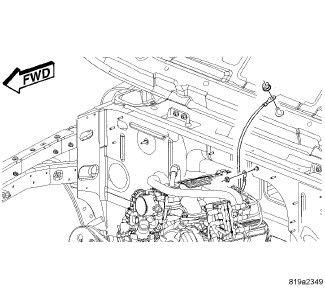 |
- Remove the screw that secures the engine-to-body ground strap eyelet to the hood panel center reinforcement.
- Remove the screw that secures the engine-to-body ground strap eyelet to the dash panel.
- Remove the nut that secures the engine-to-body ground strap eyelet to the stud on the left upper rear corner of the engine cylinder head.
- Remove the engine-to-body ground strap eyelet from the stud on the left upper rear corner of the engine cylinder head.
-
Remove the engine-to-body ground strap from the engine compartment.
INSTALLATION
INSTALLATION
ENGINE-TO-BODY GROUND STRAP
|
- Position the engine-to-body ground strap in the engine compartment.
- Position the engine-to-body ground strap eyelet over the stud on the left upper rear corner of the engine cylinder head.
- Install and tighten the nut that secures the engine-to-body ground strap eyelet to the stud on the left upper rear corner of the engine cylinder head. Tighten the nut to 5.6 N·m (50 in. lbs.).
- Install and tighten the screw that secures the engine-to-body ground strap eyelet to the dash panel. Tighten the screw to 48.5 N·m (430 in. lbs.).
-
Install and tighten the screw that secures the engine-to-body ground strap eyelet to the hood panel center reinforcement. Tighten the screw to 1.9 N·m (17 in. lbs.).