HORN
DESCRIPTION
DESCRIPTION
 |
Electromagnetic diaphragm-type horns are standard equipment on this vehicle. Vehicles manufactured with a gasoline engine have a single low note trumpet-style horn (1) secured by a mounting bracket to the back of the Front End Module (FEM) carrier in the engine compartment, directly behind the left headlamp. In Right-Hand Drive (RHD) vehicles manufactured with a diesel engine, a single low note disc-style horn (2) replaces the trumpet-style horn in the exact same mounting location. The two horn styles are nearly identical except for the molded black plastic trumpet, which is eliminated for RHD diesel engine models for clearance purposes.
Vehicles manufactured for sale in domestic markets are equipped
with a single horn system, while those manufactured for sale in many
export markets are equipped with a dual horn system. Those with the
dual horn system have a high note trumpet-style horn secured by a
mounting bracket to the back of the front bumper support beam, just
inboard of the right frame rail. The low note and high note horns
in the dual horn system are connected in parallel. Each horn in either
horn system is connected to the vehicle electrical system through
dedicated take outs and connectors of the headlamp and dash wire harness.
Each horn is serviced as a unit with the appropriate mounting bracket.
These horns cannot be adjusted or repaired. If ineffective or damaged
they must be replaced with a new unit.
OPERATION
OPERATION
The horns are connected to the vehicle electrical system through dedicated take outs and connectors of the headlamp and dash wire harness. Each horn receives a path to ground at all times through its wire harness connection to an eyelet terminal secured to the body sheet metal, and receives battery feed from an output of the Totally Integrated Power Module (TIPM) through a high side driver.
Within the two halves of the horn housing are a flexible diaphragm, a plunger, an electromagnetic coil and a set of contact points. The diaphragm is secured in suspension around its perimeter by the mating surfaces of the horn housing. The plunger is secured to the center of the diaphragm and extends into the center of the electromagnet. The contact points control the current flow through the electromagnet.
When the horn is energized, electrical current flows through the closed contact points to the electromagnet. The resulting electromagnetic field draws the plunger and diaphragm toward it until that movement mechanically opens the contact points. When the contact points open, the electromagnetic field collapses allowing the plunger and diaphragm to return to their relaxed positions and closing the contact points again. This cycle continues repeating at a very rapid rate producing the vibration and movement of air that creates the sound that is directed through the horn outlets.
The horns as well as the hard wired input circuits for the horns may be diagnosed using conventional diagnostic tools and procedures. Refer to the appropriate wiring information.
DIAGNOSIS AND TESTING - HORN
DIAGNOSIS AND TESTING - HORN
Refer to the appropriate wiring information. The wiring information includes wiring diagrams, proper wire and connector repair procedures, details of wire harness routing and retention, connector pin out information and location views for the various wire harness connectors, splices and grounds.
- Disconnect the wire harness connectors from the horn terminal connectors. Check for continuity between the horn ground circuit connector and a good ground. There should be continuity. If OK, go to Step #2. If not OK, repair the open ground circuit to ground as required.
- Check for battery voltage at the horn output circuit connector. There should be zero volts. If OK, go to Step #3. If not OK, repair the shorted horn output circuit between the horn and the Totally Integrated Power Module (TIPM) as required.
- Depress the horn switch. There should now be battery voltage at the horn output circuit connector for the horn. If OK, replace the faulty horn. If not OK, use a diagnostic scan tool and the appropriate diagnostic information for further diagnosis of the TIPM, the Local Interface Network (LIN) master node of the ElectroMechanical Instrument Cluster (EMIC) (also known as the Cab Compartment Node/CCN), the LIN slave node of the speed control switch pod, the horn switch, the LIN data bus and the CAN data bus.
REMOVAL
REMOVAL
LOW NOTE HORN
 |
| NOTE: |
A trumpet-type horn is shown; however, a disc-type horn is used on Right-Hand Drive (RHD) models equipped with a diesel engine. The service procedure is the same for either horn type. |
- Disconnect and isolate the negative cable from the battery.
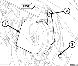
- Disconnect the two wire harness connectors from the horn (1) terminals.
- Remove the screw (2) that secures the horn mounting bracket to the back of the Front End Module (FEM) carrier (3) directly behind the left headlamp.
-
Remove the horn and
mounting bracket from the vehicle as a unit.
HIGH NOTE HORN
 |
| NOTE: |
A high note horn is used only on vehicles equipped with the dual horn system, which is used only on vehicles manufactured for certain export markets. |
- Disconnect and isolate the negative cable from the battery.
- Remove the six push pin plastic fasteners that secure the front splash shield to the frame rails and the front bumper support beam.
- Remove the front splash shield.
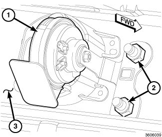
- Disconnect the two wire harness connectors from the horn (1) terminals.
- Remove the two nuts (2) that secure the horn mounting bracket to the bolts just inboard of the right frame rail on the back of the front bumper support beam (3).
-
Remove the horn and
mounting bracket from the vehicle as a unit.
INSTALLATION
INSTALLATION
LOW NOTE HORN
|
| NOTE: |
A trumpet-type horn is shown; however, a disc-type horn is used on Right-Hand Drive (RHD) models equipped with a diesel engine. The service procedure is the same for either horn type. |
- Position the horn and mounting bracket unit (1) to the back of the Front End Module (FEM) carrier (3) directly behind the left headlamp.
- Install and tighten the screw (2) that secures the horn mounting bracket to the FEM carrier. Tighten the screw securely.
- Reconnect the two wire harness connectors to the horn terminals.
-
Reconnect the negative
cable to the battery.
HIGH NOTE HORN
|
| NOTE: |
A high note horn is used only on vehicles equipped with the dual horn system, which is used only on vehicles manufactured for certain export markets. |
- Position the horn and mounting bracket unit (1) to the back of the front bumper support beam (3) with the bracket engaged over the bolts just inboard of the right frame rail.
- Install and tighten the two nuts (2) that secure the horn mounting bracket and the front bumper support beam to the fright frame rail. Tighten the nuts to 90 N·m (67 ft. lbs.).
- Reconnect the two wire harness connectors to the horn terminals.
- Position the front splash shield to the frame rails and the front bumper support beam and secure it with six push pin plastic fasteners.
-
Reconnect the negative
cable to the battery.