PLUG, Glow
DESCRIPTION
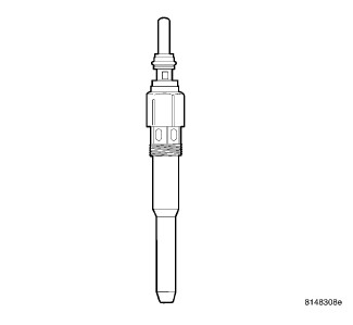
DESCRIPTION
 |
The glow plugs operate on a 5–volt
system. The glow plugs DO NOT tolerate any over voltage. Full battery
voltage will destroy the glow plug immediately. DO NOT test the glow
plugs with a 12V source as damage will occur to the glow plug.
CAUTION:
Disregarding these instructions
may cause severe engine damage.
CAUTION:
Glow plugs are used to help start a cold or cool engine. The glow plugs will heat up and glow to heat the combustion chamber of each cylinder. Each cylinder has its own glow plug which attached to cylinder head below fuel rail.
OPERATION
OPERATION
 |
The glow plugs operate on a 5–volt
system. DO NOT test the glow plugs with a 12 V source as damage will
occur to the glow plug(s).
CAUTION:
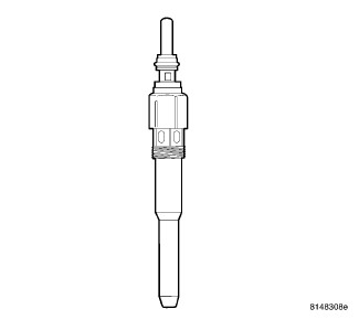
The Powertrain Control Module (PCM) monitors various engine sensors. When the ignition key is turned to the ON position, the PCM sends a signal to the glow plug module (relay) to turn on, and cycle, the glow plugs for a pre-determined amount of time, plus illuminate the glow plug light in the instrument panel. Once activated, the element inside of the core of the glow plug begins to glow. If there is a fault with the glow plug system, the PCM will store a fault code.
DIAGNOSIS AND TESTING - GLOW PLUGS
DIAGNOSIS AND TESTING - GLOW PLUGS
DO NOT attempt to start the engine
until the glow plug system tests correctly.
CAUTION:
Do not apply 12 V battery voltage
to the glow plug. Damage the glow plug, engine, or personal injury
may result.
CAUTION:
| NOTE: |
To ensure a good contact of the measurement connections the contacts have to be free of oil, dirt or corrosion. |
- Measure the electrical resistance of each glow plug while it is still installed in the cylinder head. Resistance should be between 0.2 E 5Ω between the electrical connector point on the glow plug and the cylinder head. The ground contact on the DVOM must be as close as possible to the point where the glow plug contacts the cylinder head to avoid erratic resistance measurements.
- If the resistance is out of tolerance, remove the glow plug from the cylinder head and check the resistance again.
- Dismantled state: measure between connection side (connector/thread) and housing.
- Engine mounted state: measure between connection side (connector/thread) and engine mass.
- Resistance value:
- Use the actuator test function of the scan tool to test the glow plug module and glow plug lamp. The glow plug module's on-board diagnostic tests will automatically check the electrical condition of the entire glow plug system.
- After the scan tool glow plug actuator test function is complete, if MIL is OFF and no glow plug DTCs are present, testing is complete and the engine can be started.
- If MIL is still ON, check the harness connectors of glow plugs, repair any loose or damaged connections, and run the glow plug actuator test again.
-
If MIL is still ON, check the electrical connectors of glow plugs and power up the glow plugs again.
REMOVAL
REMOVAL
 |
- Disconnect the negative battery cable.
- Remove four nuts, and the engine cover.
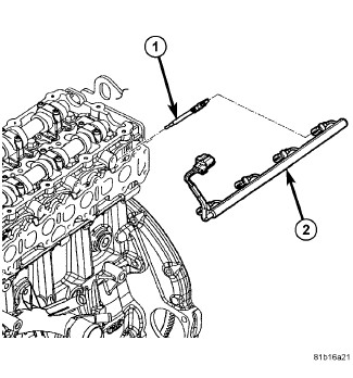
- Remove the fuel rail (Refer to 14 - Fuel System/Fuel Delivery/RAIL, Fuel - Removal) .
-
Disconnect glow plug wiring harness (2) at all four glow plugs (1).
CAUTION: After plug removal, do not bend, knock, or drop the glow plugs while handling (any mechanical impact may damage the glow plug).
-
Use a socket to loosen all the glow plug(s). After loosening, attach a flexible tool such as a rubber hose to remove glow plug from cylinder head.
INSTALLATION
INSTALLATION
|
- Apply a small amount of clean diesel oil or motor oil to glow plug threads.
- Attach a flexible tool such as a rubber hose to install glow plug into cylinder head. Tighten each plug to 14 N·m (124 in. lbs.).
- Connect glow plug wiring harness (2) to all four glow plugs (1).
- Install fuel rail (Refer to 14 - Fuel System/Fuel Delivery/RAIL, Fuel - Installation) .
-
Connect the negative battery cable.