POD, Switch
DESCRIPTION
DESCRIPTION
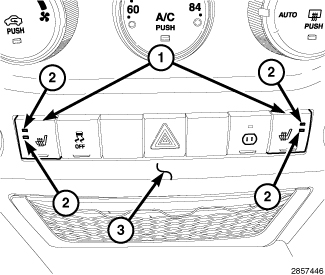
The instrument panel switch pod (1) is located just below the heater and air conditioner controls in the center stack area of the instrument panel. This switch is available in multiple configurations, which varies from two single push button switches to as many as seven push button switches, depending upon the optional equipment in the vehicle.
The pod may include the following switches:
The switch housing and the push buttons are constructed of molded plastic. Each push button has a smooth finish and is clearly identified with the appropriate text and International Control and Display Symbol icons. Several of the push buttons feature Light Emitting Diode (LED) units to give the vehicle operator an indication when the function of that switch is currently active. Only the hazard warning switch push button latches, while the remaining switches feature momentary operation.
Four screws secure the switch to the back of the instrument panel center bezel through integral mounting tabs that are molded into the body of the switch housing. The back of the switch housing has an integral connector receptacle containing terminal pins that connect the switch to the vehicle electrical system through a dedicated take out and connector of the instrument panel wire harness.
Panel lamps dimmer controlled illumination lamps integral to the circuit board within the switch provide back lighting for visibility at night, but these lamps are not serviceable. The individual switches in the lower instrument panel switch pod cannot be repaired and are not serviced separately. If any component within the switch pod is ineffective or damaged, the entire switch pod unit must be replaced.
 |
OPERATION
OPERATION
For information covering details of operation for the individual switches contained within the instrument panel switch pod, refer to the specific service information covering the system to which that switch belongs.
REMOVAL
REMOVAL
Disable the airbag system before attempting any steering wheel, steering column or instrument panel component diagnosis or service. Disconnect and isolate the negative battery (ground) cable and wait two minutes for the airbag system capacitor to discharge before performing further diagnosis or service. This is the only sure way to disable the airbag system. Failure to follow these instructions may result in accidental airbag deployment and possible serious or fatal injury.
WARNING:
| NOTE: |
Take the proper precautions to protect the face of the center bezel from cosmetic damage while performing this procedure. |
 |
- Disconnect and isolate the negative battery cable.
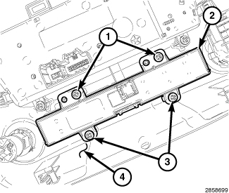
- Remove the instrument panel center bezel (4) and place it on a workbench (Refer to 23 - Body/Instrument Panel/BEZEL, Instrument Panel - Removal) .
-
Remove the four screws (1 and 3) that secure the accessory switch pod (2) to the center bezel and remove the switch pod.
INSTALLATION
INSTALLATION
| NOTE: |
Take the proper precautions to protect the face of the center bezel from cosmetic damage while performing this procedure. |
|
- Position the accesssory switch pod (2) onto the back of the instrument panel center bezel (4).
- Install the four screws (1 and 3) that secure the A/C-heater control to the center bezel. Tighten the screws to 2.2 N·m (20 in. lbs.).
- Install the instrument panel center bezel (Refer to 23 - Body/Instrument Panel/BEZEL, Instrument Panel - Installation) .
- Reconnect the negative battery cable.
-
Verify proper heated seat system operation.