SENSOR, Ambient Temperature
DESCRIPTION
DESCRIPTION
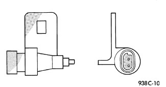 |
The ambient temperature sensor is a variable resistor type sensor. It is mounted to the lower front cross brace behind the radiator grille and in front of the engine compartment.
The ambient temperature sensor cannot be adjusted or repaired and, if inoperative or damaged, it must be replaced.
OPERATION
OPERATION
The ambient temperature sensor is a variable resistor that operates on a five-volt reference signal. The resistance in the sensor changes as temperature changes, changing the temperature sensor signal circuit voltage to the Totally Integrated Power Module (TIPM). Based upon the resistance in the sensor, the TIPM sends a voltage signal to the instrument cluster or Cab Compartment Node (CCN) over the Controller Area Network (CAN) data bus circuit, which corresponds to a specific temperature. The CCN then displays corresponding ambient temperature within the compass/temperature display unit located in the instrument cluster.
DIAGNOSIS AND TESTING - AMBIENT TEMPERATURE SENSOR
DIAGNOSIS AND TESTING - AMBIENT TEMPERATURE SENSOR
The thermometer function is supported by the ambient temperature sensor, the Totally Integrated Power Module (TIPM), the Controller Area Network (CAN) data bus circuit, and the instrument cluster or Cab Compartment Node (CCN) compass/temperature display unit.
| NOTE: |
The system displays the last known temperature when starting the vehicle and may take some time/mileage to update to an accurate current reading, up to 5 minutes at a maintained speed above 40 mph (64.3 kph). Customers with very short commutes may not get an updated reading before the vehicle is turned off, or if the ignition does not remain in the OFF position for more than 255 minutes (4hrs. 15min.). This strategy was intended to eliminate wildly fluctuating readings and may cause some customer confusion leading to unnecessary diagnostics/parts replacements. |
If the display shows " _ _ _ ", there is an OPEN or SHORT CIRCUIT that must be repaired. The ambient temperature sensor can be diagnosed using the following Sensor Test.
The most reliable, efficient and accurate means to diagnose the ambient temperature circuit requires the use of a scan tool and the proper diagnostic procedure information. Refer to wiring for the appropriate information.
SENSOR TESTING
- Turn the ignition switch to the OFF position. Disconnect and isolate the battery negative cable.
- Disconnect the ambient temperature sensor wire harness connector.
- Measure the resistance of the ambient temperature sensor. At room temperature (approx. 20° C (68°F)), the sensor resistance should be between 9-11 Kilohms (9000-11000 ohms). The sensor resistance should read between these two values. If OK, refer to the appropriate diagnostic information to continue diagnosis of the Totally Integrated Power Module (TIPM), the Controller Area Network (CAN) data bus circuit, and the instrument cluster or CCN. If not OK, replace the inoperative ambient temperature sensor.
REMOVAL
REMOVAL
 |
- Disconnect and isolate the battery negative cable.
- Remove the grille assembly (Refer to 23 - Body/Exterior/GRILLE - Removal) .
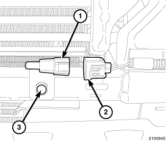
- Disconnect the wire harness connector (2) from the ambient temperature sensor (1).
- Remove the retainer (3) that secures the ambient temperature sensor bracket to the lower cross brace.
-
Remove the ambient temperature sensor from the vehicle.
INSTALLATION
INSTALLATION
|
- Position the ambient temperature sensor in the vehicle.
- Install the retainer (3) that secures the ambient temperature sensor to the lower cross brace.
- Connect the wire harness connector (2) to the ambient temperature sensor (1).
- Install the grille assembly (Refer to 23 - Body/Exterior/GRILLE - Installation) .
-
Connect the battery negative cable.