SWITCH, Hood Ajar
- DESCRIPTION
- SINGLE BRACKET
- DUAL BRACKET
- SINGLE SWITCH
- DUAL SWITCH
- SINGLE BRACKET
- DUAL BRACKET
- SINGLE SWITCH
- DUAL SWITCH
DESCRIPTION
DESCRIPTION
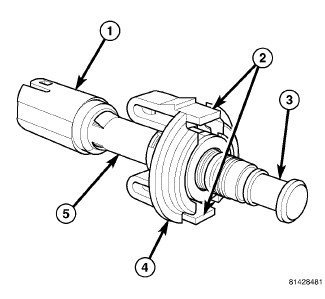 |
The hood ajar switch is a normally closed, single pole, spring-loaded plunger actuated switch. This switch has two unique versions that are used in two different applications. One switch is used only on vehicles equipped with the STOP/START system for sale in certain export markets where protection of the under hood area is required equipment. The second switch is used only on domestic vehicles equipped with an optional remote starter system.
The molded plastic switch body (5) has an integral molded connector receptacle (1) on the lower end containing two terminal pins. The switch is connected to the vehicle electrical system through a dedicated take out of the engine compartment wire harness. Two integral latches (2) lock the switch into a keyed mounting hole in the stamped steel switch mounting bracket. The mounting bracket is secured with a screw to the forward end of the left load beam in the left front corner of the engine compartment. The underside of the hood panel inner reinforcement actuates the switch plunger as the hood panel is closed.
The switch plunger (3) extends through a mounting collar (4) and a sleeve-like retainer ring on the upper end of the switch body. The retainer ring has a one time, self-adjustment feature that is activated after the switch is installed by closing the hood. The retainer ring is also color-coded to aid in identifying the switch application. A dark brown retainer ring identifies the under hood STOP/START switch application, while a white retainer ring identifies the remote starter system application.
An installed hood ajar switch cannot be readjusted or repaired.
If the switch is damaged, ineffective, or requires readjustment, it
must be replaced with a new unit.
SINGLE BRACKET
SINGLE BRACKET
 |
- Disconnect and isolate the negative cable or the Intelligent Battery Sensor (IBS) and negative cable assembly (as equipped) from the negative terminal post of the battery.
-
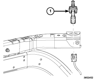
Remove the remote start
hood ajar switch (1) from the mounting bracket. (Refer to 08 - Electrical/8Q - Vehicle
Theft Security/SWITCH, Hood Ajar - Removal)
.
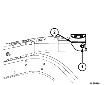
- Remove the screw (1) that secures the remote start hood ajar switch bracket (2) to the front of the left front load beam in the engine compartment.
-
Remove the hood ajar
switch bracket (2) from the load beam.
DUAL BRACKET
DUAL BRACKET
 |
- Disconnect and isolate the negative cable or the Intelligent Battery Sensor (IBS) and negative cable assembly (as equipped) from the negative terminal post of the battery.
-
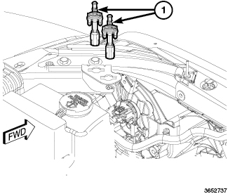
Remove the remote start
and stop/start hood ajar switches (1) from the mounting bracket. (Refer to 08 - Electrical/8Q - Vehicle
Theft Security/SWITCH, Hood Ajar - Removal)
.
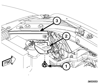
- Remove the screw (1) that secures the mounting bracket (2) to the left front load beam (3) in the engine compartment.
-
Remove the hood ajar
switch mounting bracket (2) from the load beam.
SINGLE SWITCH
SINGLE SWITCH
 |
- Open the hood.
- Disconnect and isolate the negative battery cable.
- Disconnect the IBS/negative battery cable assembly from the negative battery post.
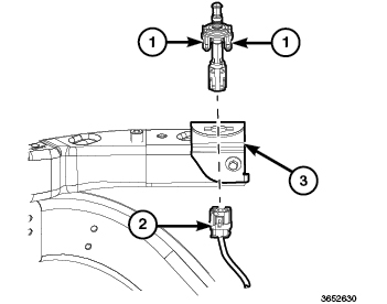
- From the top of the mounting bracket (3) in the left front corner of the engine compartment, squeeze the two remote start hood ajar switch latch tabs (1) together and pull the switch upward.
- Pull the remote start hood ajar switch up through the hole in the mounting bracket (3) far enough to access and disconnect the harness connector (2) from the switch connector receptacle.
-
Remove the remote start
hood ajar switch from the engine compartment.
DUAL SWITCH
DUAL SWITCH
 |
- Open the hood.
- Disconnect the IBS/negative battery cable assembly from the negative battery post.
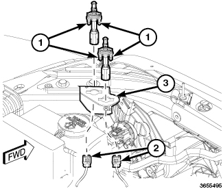
- From the top of the mounting bracket (3) in the left front corner of the engine compartment, squeeze the two Remote Start and Stop/Start switch latch tabs (1) together and pull the switch upward.
- Pull the Remote Start and Stop/Start switch up through the hole in the mounting bracket far enough to access and disconnect the harness connector (2) from the switch connector receptacle.
-
Remove the Remote Start
and Stop/Start switch from the engine compartment.
SINGLE BRACKET
SINGLE BRACKET
|
- Position the remote start hood ajar switch bracket (2) to the left front load beam in the engine compartment.
-
Install and tighten
the screw (1) that secures the bracket to the load beam. Tighten the
screw to 8 N·m (71 in. lbs.).
- Reinstall the remote start hood ajar switch (1) into the mounting bracket. (Refer to 08 - Electrical/8Q - Vehicle Theft Security/SWITCH, Hood Ajar - Installation) .
-
Reinstall the negative
cable or the Intelligent Battery Sensor (IBS) and negative cable assembly
(as equipped) to the negative terminal post of the battery.
DUAL BRACKET
DUAL BRACKET
|
- Position the remote start and stop/start hood ajar switch mounting bracket (2) to the left front load beam (3) in the engine compartment.
-
Install and tighten
the screw (1) that secures the mounting bracket to the load beam (3).
Tighten the screw to 8 N·m (71 in. lbs.).
- Reinstall the remote start and stop/start hood ajar switches into the mounting bracket. (Refer to 08 - Electrical/8Q - Vehicle Theft Security/SWITCH, Hood Ajar - Installation) .
-
Reinstall the negative cable or the Intelligent Battery Sensor
(IBS) and negative cable assembly (as equipped) to the negative terminal
post of the battery.
SINGLE SWITCH
SINGLE SWITCH
|
- Position the remote start hood ajar switch near the hole in the mounting bracket (3) on the front of the left load beam in the left front corner of the engine compartment.
- Route the harness connector (2) through the switch mounting bracket (3) and connect it to the switch connector receptacle.
- From the top of the mounting bracket, press the switch downward into the mounting hole until the integral switch latch tabs lock it into place.
- If equipped with IBS, connect the IBS/negative battery cable assembly to the negative battery post.
- Connect the negative battery cable.
-
Close and latch the
hood.
DUAL SWITCH
DUAL SWITCH
|
- Position the Remote Start and Stop/Start switches near the hole in the mounting bracket (3) on the front of the left load beam (1) in the left front corner of the engine compartment.
- Route the harness connector (2) through the switch mounting bracket (3) and reconnect it to the switch connector receptacles.
- From the top of the mounting bracket, press the switch downward into the mounting hole until the integral switch latch tabs lock it into place.
- Connect the IBS/negative battery cable assembly to the negative battery post.
- Connect the negative battery cable.
-
Close and latch the
hood.