ARM, Wiper
FRONT
FRONT
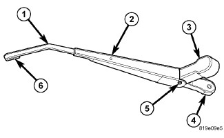 |
The front wiper arms are the rigid members located between the
wiper pivots that protrude from the cowl plenum cover/grille panel
near the base of the windshield and the wiper blades on the windshield
glass. These wiper arms feature an over-center hinge (5) that allows
easy access to the windshield glass for cleaning. The wiper arm has
a die cast metal pivot end (4) with a large tapered mounting hole
at one end. A molded black plastic cap (3) snaps over the pivot end
to conceal the retaining nut and mounting hole following wiper arm
installation.
The wide end of a tapered, stamped steel channel (2) hinges on and is secured with a hinge pin to the blade end of the wiper arm pivot end. One end of a long, rigid, stamped steel strap (1), with a small hole near the end closest to the pivot, is riveted and crimped within the narrow end of the stamped steel channel. The tip of the wiper blade end of this strap is bent back under itself to form a small hook (6). Concealed within the stamped steel channel is a long tension spring which is engaged with a wire hook to the underside of the die cast pivot end and is hooked through a small hole in the steel strap. The entire wiper arm has a satin black finish applied to all of its visible surfaces.
There are unique wiper arms for right-hand-drive and left-hand-drive
vehicles. The driver and passenger side arms are interchangeable.
A wiper arm cannot be adjusted or repaired and, if ineffective or
damaged, it must be replaced.
REAR
REAR
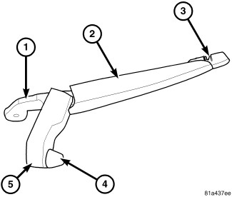 |
The rear wiper arm (2) is the rigid member located between the rear wiper motor output shaft that protrudes through a rubber nut cover near the upper left corner of the lift glass and the wiper blade on the outside of the glass. The wiper arm is constructed of molded black plastic. A hinged pivot end (1) is also molded plastic.
A molded black plastic nut cover (5) with two pivot pins on one end and a snap feature on the other fits over the wiper arm retaining nut to conceal the nut and mounting hole following wiper arm installation. The rear washer nozzle integral to the motor output shaft is aimed through a large hole (4) in the side of the nut cover oriented towards the downward path of the wiper blade. The wiper arm hinge and tension spring are concealed on the underside of the wide end of the arm, while integral latch features (3) concealed on the underside of the narrow end of the wiper arm accept the pivot pin of the matching molded plastic wiper blade unit.
The rear wiper arm cannot be adjusted or repaired. If damaged or
ineffective, the entire wiper arm unit must be replaced.
FRONT
FRONT
The front wiper arms are designed to mechanically transmit the motion from the wiper pivots to the wiper blades. The wiper arm must be properly indexed to the wiper pivot in order to maintain the proper wiper blade travel on the glass. The tapered mounting hole in the wiper arm pivot end interlocks with the serrations on the tapered outer circumference of the wiper pivot shaft, allowing positive engagement and finite adjustment of this connection.
The mounting nuts lock the wiper arms to the threaded studs of the wiper pivot shafts. The spring-loaded wiper arm hinge controls the down-force applied through the tip of the wiper arm to the wiper blade on the glass. The hook formation on the tip of the wiper arm provides a cradle for securing and latching the wiper blade pivot block to the wiper arm.
REAR
REAR
The rear wiper arm is designed to mechanically transmit the motion from the rear wiper motor output shaft to the rear wiper blade. The wiper arm must be properly indexed to the motor output shaft in order to maintain the proper wiper blade travel on the glass. The tapered hole in the wiper arm pivot end interlocks with the serrations on the outer circumference of the tapered motor output shaft, allowing positive engagement and finite adjustment of this connection.
A hex nut secures the wiper arm pivot end to the threads on the rear wiper motor output shaft and the plastic cover snaps over this connection for a neat appearance. The spring-loaded wiper arm hinge controls the down-force applied through the tip of the wiper arm to the wiper blade on the glass. The latch formation on the tip of the wiper arm provides a cradle for securing and latching the wiper blade pivot pin to the wiper arm.
FRONT
FRONT
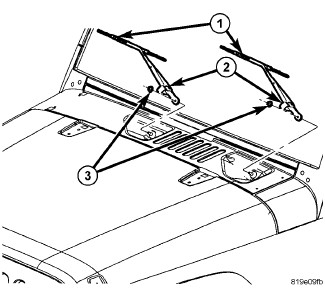 |
- Lift the front wiper arm (1) to its over-center position to hold the wiper blade off of the glass and relieve the spring tension on the wiper arm to pivot shaft connection.
- Carefully unsnap the plastic cap (2) off of the pivot end of the wiper arm and swing it out of the way.
-
Remove the nut (3)
that secures the wiper arm to the wiper pivot shaft.
CAUTION: The use of a battery terminal puller when removing the front wiper arm is NOT recommended as this may damage the front wiper arm.
-
Use a slight rocking
action to disengage the front wiper arm pivot end from the pivot shaft
and remove the wiper arm.
REAR
REAR
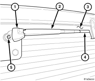 |
- Unsnap and swing the molded plastic nut cover (1) off of the pivot end of the wiper arm (2).
-
Remove the nut (5)
that secures the wiper arm to the rear wiper motor output shaft.
CAUTION: The use of a battery terminal puller when removing the rear wiper arm is NOT recommended as this may damage the rear wiper arm.
-
Use a slight rocking
action to disengage the rear wiper arm pivot end from the output shaft
and remove the wiper arm.
FRONT
FRONT
|
| NOTE: |
Be certain that the wiper motor is in the park position before attempting to install the front wiper arms. Turn the ignition switch to the ON position and move the right (wiper) multi-function switch control knob to its OFF position. If the wiper pivots move, wait until they stop moving, then turn the ignition switch back to the OFF position. The front wiper motor is now in its park position. |
- The front wiper arms (1) must be indexed to the pivot shafts with the front wiper motor in the park position to be properly installed. Position the wiper arm pivot end onto the wiper pivot shaft so that the lug on the pivot shaft engages the pocket on the underside of the wiper arm pivot end.
- Once the wiper blade is aligned, lift the wiper arm away from the windshield slightly to relieve the spring tension on the pivot end and push the pivot end of the wiper arm down firmly and evenly over the pivot shaft.
- Install and tighten the nut (3) that secures the wiper arm to the pivot shaft. Tighten the nut to 23 N·m (17 ft. lbs.).
-
Snap the plastic cap
(2) over the wiper arm pivot end.
REAR
REAR
|
| NOTE: |
Be certain that the rear wiper motor is in the park position before attempting to install the rear wiper arm. Turn the ignition switch to the ON position and move the rear wiper switch to its OFF position. If the wiper motor output shaft moves, wait until it stops moving, then turn the ignition switch back to the OFF position. The wiper motor is now in its park position. |
- The rear wiper arm (2) must be indexed to the rear wiper motor output shaft with the motor in the park position to be properly installed. Position the wiper arm pivot end onto the output shaft so that the wiper arm is horizontal and the tip of the wiper blade is midway between the uppermost horizontal line (4) of the rear window defogger grid and the lower edge of the upper glass blackout area (3).
- With the rear wiper arm properly indexed, push the tapered mounting hole on the pivot end of the wiper arm down over the output shaft.
- Install and tighten the nut (5) that secures the rear wiper arm to the output shaft. Tighten the nut to 19.5 N·m (14 ft. lbs.).
- Fold and snap the molded plastic nut cover (1) over the nut on the pivot end of the rear wiper arm.
-
Wet the lift glass
and operate the rear wiper. Turn the rear wiper switch to the OFF
position, then check for correct wiper arm position and readjust as
required.