CLUTCH, B2
DISASSEMBLY
DISASSEMBLY
Special Tools: Click to display a list of tools used in this procedure
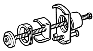
- Remove snap ring (1) .
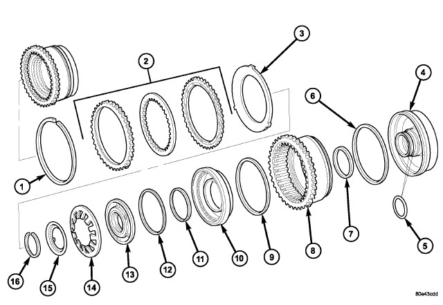
- Take multiple-disc pack B2 (2) and disc spring (3) out of the outer multiple-disc carrier B2 (8). The outer multiple-disc carrier for the multi-disc holding clutch B2 is the piston for the multiple-disc holding clutch B3 at the same time. Note which clutch disc is removed just prior to the disc spring (3) for re-assembly. If the clutch discs are re-used, this disc must be returned to its original position on top of the disc spring.
- Place the Multi-use Spring Compressor 8900A on the spring disc (14) and compress the spring until the groove for the snap-ring is exposed.
- Remove snap-ring (16) .
-
Remove spring plate (15) and disc spring (14).
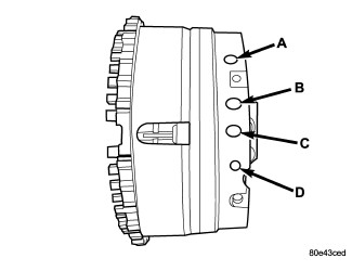
- Separate piston guide ring (13) and the B2 piston (10) from the B3 piston (8) by blowing compressed air into the bore (D) .
- Press piston guide ring (13) out of the B2 piston (10).
-
Separate piston guide (4) from the B3 piston (8) by blowing compressed air into the bore (A) .
ASSEMBLY
ASSEMBLY
Special Tools: Click to display a list of tools used in this procedure
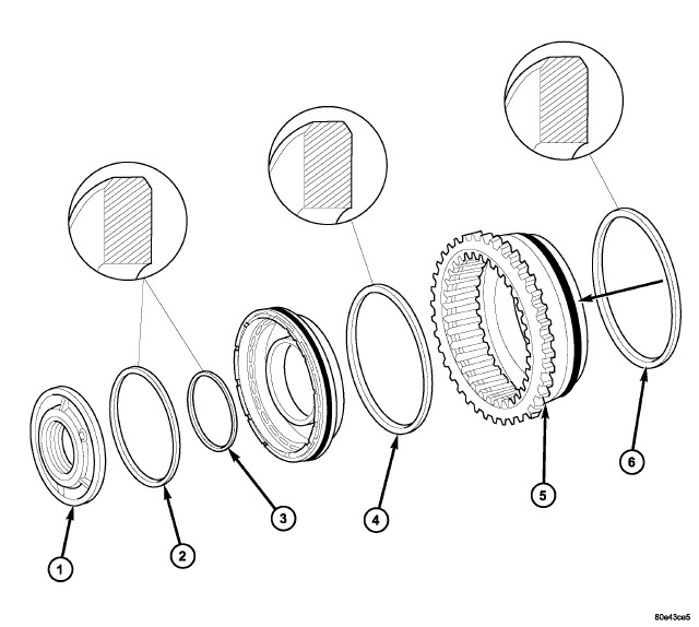
-
Check all sealing rings
(2-4, 6) , replace if necessary.
The rounded off edges on the sealing rings (2, 4, 6) must point outwards.
- Assemble piston guide (4) and B3 piston (8) in the correct position. Verify that the missing tooth in the B3 piston/B2 outer disc carrier (8) is aligned with the centerline of the two threaded holes in the B2 and B3 piston guide (4).
-
Insert B2 piston (10) in B3 piston (8).
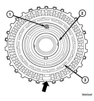
-
Insert piston guide
ring (2) . The valve (1) in the
piston guide ring must be on top.
- Insert disc spring (14) and spring plate (15). Insert disc spring with the curvature towards the spring plate
- Place Multi-use Spring Compressor 8900A on the disc spring (14) and compress the spring until the groove for the snap-ring is exposed.
-
Insert snap-ring (16).
NOTE: Pay attention to sequence of discs. If the original clutch discs are reused, be sure to return the disc identified on disassembly as belonging on top of the disc spring (3) to its original location. Place new friction multiple-discs in ATF fluid for one hour before installing.
- Insert disc spring (3) and multiple-disc pack (2) in the B2 outer multiple-disc carrier.
-
Insert snap-ring (1).
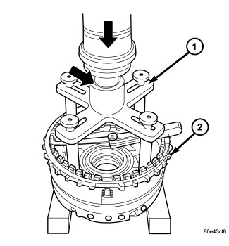
NOTE: During the measurement the snap-ring must contact the upper bearing surface of the groove in the outer multiple-disc carrier.
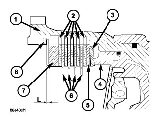
- Measure the B2 clutch pack clearance by mounting the Pressing Tool 8901A (1) on outer multiple disc.
-
Using a lever press,
compress pressing tool to the upper most line marked 1200 N (the marking
ring is still visible, see small arrow).
- Using a feeler gauge, determine the play "L" at three points between the snap-ring (8) and outer multiple-disc (7).
- The correct clutch clearance is 1.9-2.3 mm (0.075-0.091 in.) for the four friction disc versions and 2.0-2.4 mm (0.079-0.095 in.) for the five disc versions.
-
Adjust with snap-ring
(8), if necessary. Snap-rings are available in thicknesses of 2.9
mm (0.114 in.), 3.2 mm (0.126 in.), 3.5 mm (0.138 in.), 3.8 mm (0.150
in.), and 4.1 mm (0.162 in.).