SENSOR, Speed
DESCRIPTION
DESCRIPTION
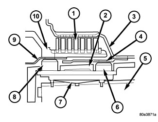 |
The speed sensors, N2 and N3, (6, 8) are fixed to the shell of the electrohydraulic control unit's leadframe via contact blades. The speed sensors are pressed against the transmission housing (2) by a spring (7) which is held against the valve housing of the shift plate (5). This ensures a defined distance between the speed sensors and the exciter ring (4).
OPERATION
OPERATION
|
Signals from the speed sensors, N2 and N3, (6, 8) are recorded in the transmission control module (TCM), together with the wheel and engine speeds and other information, and are processed into an input signal for electronic control.
Speed sensor N2 (6) records the speed of the front planetary rear annulus assembly (10). Speed sensor N3 (8) records the speed of the K1 clutch (3).
RELATIVE SPEED SENSOR READINGS - NAG 1 TRANSMISSION
|
There are several things to note regarding the function of the N2 and N3 speed sensors.
- K1 clutch (N3 speed sensor) will show no rotation whenever the B1 Brake is applied. N3 = Zero in 1st, 5th and Reverse.
- With the vehicle moving forward or reverse, N2 speed sensor reading will be greater than zero in all gears
- Whenever the K1 clutch is applied (2nd, 3rd, and 4th) N2 will be equal to N3.
- There is no speed sensor internal to the transmission that directly measures input shaft speed. However, when K1 is applied N2 equals input shaft/turbine speed.
- The engine speed is fed to the TCM via can bus thus providing impeller speed.
- There is no speed sensor internal to the transmission that directly measures output shaft speed. ABS wheel sensors provide output shaft speed.
- K1 clutch (N3 speed sensor) will show no rotation whenever the B1 Brake is applied. N3 is equal to zero in 1st, 5th and Reverse gears.
- With the vehicle moving forward or reverse, N2 speed sensor reading will be greater than zero in all gears.
- Whenever the K1 clutch is applied (2nd, 3rd, and 4th) N2 will be equal to N3.
- There is no speed sensor internal to the transmission that directly measures input shaft speed. However, when K1 is applied N2 equals input shaft/turbine speed.
- The engine speed is fed to the TCM via the vehicle's communication bus thus providing impeller speed.
- There is no speed sensor internal to the transmission that directly measures output shaft speed. ABS wheel sensors provide output shaft speed.
| NOTE: |
N2 sensor, N3 sensor, output shaft speed sensor are speeds relative to the input shaft turbine speed. |
| GEAR | INPUT SHAFT/TURBINE SPEED | N2 SENSOR | N3 SENSOR | OUTPUT SHAFT SPEED | OVERALL RATIO |
|---|---|---|---|---|---|
|
1ST |
1.0000 |
0.6081 |
0.0000 |
0.2782 |
3.59 |
|
2ND |
1.0000 |
1.0000 |
1.0000 |
0.4574 |
2.19 |
|
3RD |
1.0000 |
1.0000 |
1.0000 |
0.7115 |
1.41 |
|
4TH |
1.0000 |
1.0000 |
1.0000 |
1.0000 |
1.00 |
|
5TH |
1.0000 |
0.6081 |
0.0000 |
1.2035 |
0.83 |
|
REVERSE(S) |
1.0000 |
0.6081 |
0.0000 |
-0.3157 |
-3.17 |
Based on the preceding chart, it appears that N3 sensor is redundant and provides no additional information. However, the TCM needs to know Input Shaft/Turbine speed. Since the N2 sensor is not directly tied to the Input Shaft, the N3 sensor is required to inform the TCM to divide the N2 value by 0.6081 or 1.0000 to calculate actual Turbine speed.