CABLES, Battery
DIAGNOSIS AND TESTING - BATTERY CABLES
DIAGNOSIS AND TESTING - BATTERY CABLES
A voltage drop test will determine if there is excessive resistance in the battery cable terminal connections or the battery cable. If excessive resistance is found in the battery cable connections, the connection point should be disassembled, cleaned of all corrosion or foreign material, then reassembled. Following reassembly, check the voltage drop for the battery cable connection and the battery cable again to confirm repair.
When performing the voltage drop test, it is important to remember that the voltage drop is giving an indication of the resistance between the two points at which the voltmeter probes are attached. EXAMPLE: When testing the resistance of the battery positive cable, touch the voltmeter leads to the battery positive cable terminal clamp and to the battery positive cable eyelet terminal at the starter solenoid B(+) terminal stud. If you probe the battery positive terminal post and the battery positive cable eyelet terminal at the starter solenoid B(+) terminal stud, you are reading the combined voltage drop in the battery positive cable terminal clamp-to-terminal post connection and the battery positive cable.
VOLTAGE DROP TEST
The following operation will require a voltmeter accurate to 1/10 (0.10) volt. Before performing this test, be certain that the following procedures are accomplished:
- The battery is fully-charged and load tested. Refer to Standard Procedures for the proper battery charging and load test procedures.
- Fully engage the parking brake.
- If the vehicle is equipped with an automatic transmission, place the gearshift selector lever in the Park position. If the vehicle is equipped with a manual transmission, place the gearshift selector lever in the Neutral position and block the clutch pedal in the fully depressed position.
- Verify that all lamps and accessories are turned off.
- To prevent the engine from starting, remove the Automatic Shut Down (ASD) relay. The ASD relay can be found in the Fuse Block located in the left front bumper fascia. See the fuse and relay layout label affixed to the underside of the Fuse Block cover for ASD relay identification and location.
 |
-
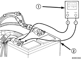
Connect the positive lead of the voltmeter (1) to the battery (2) negative terminal post. Connect the negative lead of the voltmeter (1) to the battery (2) negative cable terminal clamp. Rotate and hold the ignition switch in the Start position. Observe the voltmeter. If voltage is detected, correct the poor connection between the battery negative cable terminal clamp and the battery negative terminal post.
-
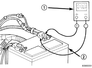
Connect the positive lead of the voltmeter (1) to the battery (2) positive terminal post. Connect the negative lead of the voltmeter (1) to the battery (2) positive cable terminal clamp. Rotate and hold the ignition switch in the Start position. Observe the voltmeter. If voltage is detected, correct the poor connection between the battery positive cable terminal clamp and the battery positive terminal post.
-
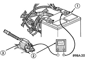
Connect the voltmeter (2) to measure between the battery positive cable terminal clamp (1) and the starter solenoid B(+) terminal stud (3). Rotate and hold the ignition switch in the Start position. Observe the voltmeter. If the reading is above 0.2 volt, clean and tighten the battery positive cable eyelet terminal connection at the starter solenoid B(+) terminal stud. Repeat the test. If the reading is still above 0.2 volt, replace the faulty battery positive cable.
-
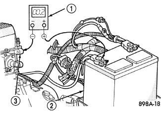
Connect the voltmeter (1) to measure between the battery (2) negative cable terminal clamp and a good clean ground on the engine block (3). Rotate and hold the ignition switch in the Start position. Observe the voltmeter. If the reading is above 0.2 volt, clean and tighten the battery negative cable eyelet terminal connection to the engine block. Repeat the test. If the reading is still above 0.2 volt, replace the faulty battery negative cable.
REMOVAL
REMOVAL
 |
Remove metallic jewelry to avoid injury by accidental arcing of battery current.
WARNING:
The battery negative and positive cable polarity are different from the gasoline engine equipped vehicles to the diesel engine equipped vehicles. Please note the location of the positive and negative cables prior to service of the battery or related components.
WARNING:
| NOTE: |
Left hand drive gasoline engine shown, left hand drive diesel similar. Right hand drive gasoline and diesel similar with the battery and related components packaged on the left side of the engine compartment. |
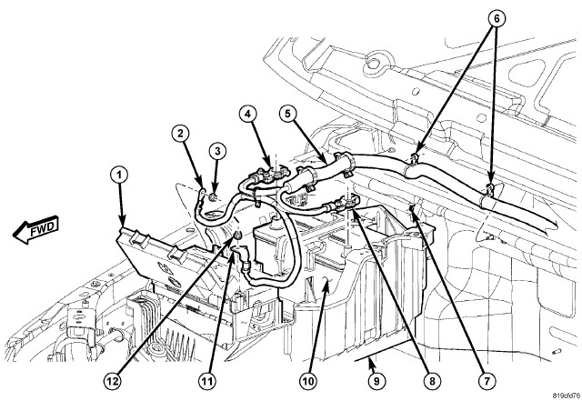
- Loosen the pinch clamp bolt and disconnect and isolate the battery negative cable (8).
- Loosen the pinch clamp bolt and disconnect the battery positive cable (4).
- Remove the positive cable retaining nut (12) from the mounting stud on the Totally Integrated Power Module (1). Remove the cable (11) from the stud.
- Remove the negative cable retaining nut (3) from the mounting stud on the inner fender. Remove the cable (2) from the stud.
-
Disconnect the cable assembly (5) routing clips (6) from the mounting studs (7).
-
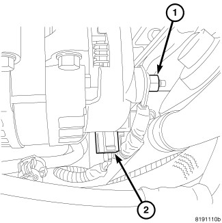
Remove the battery cable nut (1) from the B+ terminal of the generator. Remove the cable from the generator.
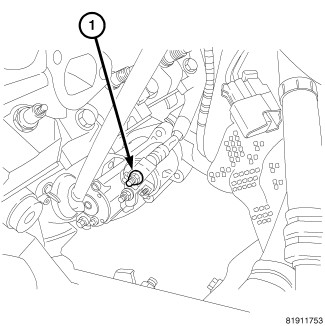
- Remove the battery cable from the B+ terminal of the starter motor (1).
- Remove the negative battery cable from the engine block ground.
- One at a time, trace any remaining battery cable retaining pushpins, fasteners and routing clips until the cables are free from the vehicle.
-
Remove the battery cables from the engine compartment.
INSTALLATION
INSTALLATION
|
Remove metallic jewelry to avoid injury by accidental arcing of battery current.
WARNING:
- Position the battery cables in the engine compartment.
- One at a time, install the battery cable retaining pushpins, fasteners and routing clips until the cables are installed exactly where they were in the vehicle.
- Install the negative battery cable to the engine block ground.
-
Connect the battery cable to the B+ terminal of the starter motor (1). Tighten the cable nut to 13 N·m (115 in. lbs.).
-
Connect the battery cable to the B+ terminal of the generator (1). Tighten the cable nut to 14 N·m (125 in. lbs.).
WARNING: The battery negative and positive cable polarity are different from the gasoline engine equipped vehicles to the diesel engine equipped vehicles. Please note the location of the positive and negative cables prior to service of the battery or related components.
NOTE: Left hand drive gasoline engine shown, left hand drive diesel similar. Right hand drive gasoline and diesel similar with the battery and related components packaged on the left side of the engine compartment.
- Connect the cable assembly (5) routing clips (6) to the mounting studs (7).
- Install the nut (3) securing the negative cable (2) to the body ground stud. Tighten the cable nut to 12 N·m (9 ft. lbs.)
- Install the nut (12) securing the Totally Integrated Power Module (TIPM) cable (11) to the battery cable stud (5).
- Connect the battery positive cable (4). Tighten the cable clamp nut to 5 N·m (45 in. lbs.)
-
Connect the battery negative cable (8). Tighten the cable clamp nut to 5 N·m (45 in. lbs.)