ACTUATOR, Recirculation Door
DESCRIPTION
DESCRIPTION
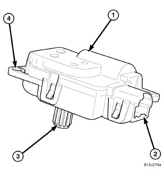 |
The recirculation door actuator (1) is a reversible, 12 volt direct current (DC) servo motor, which is connected directly to the pivot shaft lever of the recirculation-air door. The recirculation door actuator is located on the right side of the HVAC air inlet housing.
The recirculation door actuator is contained within a black molded plastic housing with an integral wire connector receptacle (2), an output shaft with splines (3) that connect it to the recirculation door and three integral mounting tabs (4) that allow the actuator to be secured to the air inlet housing. The recirculation door actuator does not require mechanical indexing to the recirculation-air door, as it is electronically calibrated by the A/C-heater control.
OPERATION
OPERATION
The recirculation door actuator is connected to the A/C-heater control through the vehicle electrical system by a dedicated two-wire lead and connector of the instrument panel wire harness. The recirculation door actuator can move the recirculation-air door in two directions. When the A/C-heater control pulls the voltage on one side of the motor connection high and the other connection low, the recirculation-air door will move in one direction. When the A/C-heater control reverses the polarity of the voltage to the motor, the recirculation-air door moves in the opposite direction. Once the A/C-heater control makes the voltage to both connections high or both connections low, the recirculation-air door stops and will not move.
The recirculation door actuator cannot be adjusted or repaired and it must be replaced if inoperative or damaged.
REMOVAL
REMOVAL
Disable the airbag system before
attempting any steering wheel, steering column or instrument panel
component diagnosis or service. Disconnect and isolate the negative
battery (ground) cable, then wait two minutes for the airbag system
capacitor to discharge before performing further diagnosis or service.
This is the only sure way to disable the airbag system. Failure to
follow these instructions may result in accidental airbag deployment
and possible serious or fatal injury.
WARNING:
| NOTE: |
LHD model shown. RHD model similar. |
 |
| NOTE: |
Illustration shown with instrument panel removed for clarity. |
- Disconnect and isolate the negative battery cable.
- Remove the silencer panel and glove box from the passenger side of the instrument panel.
- On LHD models, remove the speaker from the passenger side of the instrument panel (Refer to 08 - Electrical/8A - Audio and Video/SPEAKER - Removal) .
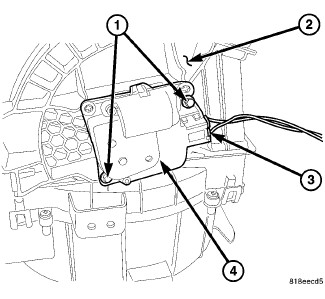
- Reach through glove box opening in the instrument panel and remove the screws (1) that secure the recirculation door actuator (4) to the right side of the HVAC air inlet housing (2).
- Remove the recirculation door actuator from the air inlet housing and disconnect the wire harness connector (3) from the actuator.
-
Remove the recirculation door actuator from the vehicle.
INSTALLATION
INSTALLATION
| NOTE: |
LHD model shown. RHD model similar. |
|
| NOTE: |
Illustration shown with instrument panel removed for clarity. |
- Connect the wire harness connector (3) to the mode door actuator (4).
- Position the recirculation door actuator onto the right side of the HVAC air inlet housing (2). If necessary, rotate the actuator slightly to align the splines on the actuator output shaft with those on the recirculation door pivot shaft adapter.
- Install the two screws (1) that secure the recirculation door actuator to the air inlet housing. Tighten the screws to 1.2 N·m (10 in. lbs.).
- Verify the wire harness connector is securely attached to the recirculation door actuator.
- On LHD models, install the speaker to the passenger side of the instrument panel (Refer to 08 - Electrical/8A - Audio and Video/SPEAKER - Installation) .
- Install the glove box and silencer panel.
- Reconnect the negative battery cable.
-
Initiate the Actuator Calibration function using a scan tool (Refer to 28 - DTC-Based Diagnostics/HVAC - Standard Procedure)
.