CONTROL, A/C and Heater
- AUTOMATIC TEMPERATURE CONTROL (ATC) SYSTEM
- MANUAL TEMPERATURE CONTROL (MTC) SYSTEM
- REMOVAL
- INSTALLATION
AUTOMATIC TEMPERATURE CONTROL (ATC) SYSTEM
AUTOMATIC TEMPERATURE CONTROL (ATC) SYSTEM
 |
The Automatic Temperature Control (ATC) single zone heating-A/C system uses electrically operated controls. These controls provide the operator with a number of setting options to help control the climate and comfort within the vehicle.
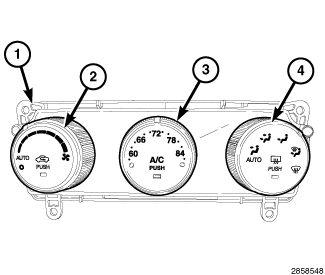
The A/C-heater control (1) for the ATC single zone system automatically maintains the interior comfort level desired by the operator. The ATC system automatically adjusts air temperature, airflow volume, airflow distribution and amount of inside air recirculation required to maintain occupant comfort, even under changing outside weather conditions. All controls are identified by International Standardization Organization (ISO) graphic symbols.
This ATC system offers several manual override features such as fan speed and airflow distribution. When the outside air contains smoke, odors, high humidity, or if rapid cooling is desired, the interior conditioned air can be recirculated within the vehicle.
The ATC A/C-heater control and integral computer is located in the instrument panel and contains:
- a rotary control for manual and automatic blower motor speed selection and for turning the heating-A/C system on and off (2). This control also contains a push button function for recirculating the conditioned air. The control contains an indicator lamp that illuminates when the heating-A/C system is in recirculation mode.
- a rotary control for temperature control of the discharged air (3). This control also contains a push button function for manually turning the A/C system on and off. The control contains an indicator lamp that illuminates when the A/C system is in operation.
- a rotary control for manual and automatic mode control of the discharged air (4). This control also contains a push button function for turning the rear window defogger system on and off. The control contains an indicator lamp that illuminates when the rear window defogger system is in operation.
The ATC A/C-heater control obtains vehicle speed, engine speed, engine coolant temperature, ambient temperature and refrigerant system head pressure data and is diagnosed using a scan tool (Refer to 28 - DTC-Based Diagnostics/HVAC - Diagnosis and Testing) .
Prior to replacing the A/C-heater control, check for any Diagnostic Trouble Codes (DTCs) related to the heating-A/C system and run the Actuator Calibration function using a scan tool to verify that the concern is not an air door calibration issue (Refer to 28 - DTC-Based Diagnostics/HVAC - Standard Procedure) .
The A/C-heater control cannot be adjusted or repaired and must be replaced if inoperative or damaged.
MANUAL TEMPERATURE CONTROL (MTC) SYSTEM
MANUAL TEMPERATURE CONTROL (MTC) SYSTEM
 |
The Manual Temperature Control (MTC) single zone heating-A/C system uses electrically operated controls. These controls provide the vehicle operator with a number of setting options to help control the climate and comfort within the vehicle.
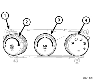
The A/C-heater control (1) for the MTC single zone system allows one temperature setting for the entire vehicle. All controls are identified by International Standardization Organization (ISO) graphic symbols.
The MTC A/C-heater control and integral computer is located in the instrument panel and contains:
- a rotary control for fan speed selection and for turning the heating-A/C system on and off (2). This control also contains a push button function for recirculating the conditioned air. The control contains an indicator lamp that illuminates when the heating-A/C system is in recirculation mode.
- a rotary control for temperature control of the discharged air (3). This control also contains a push button function for turning the A/C system on and off. The control contains an indicator lamp that illuminates when the A/C system is in operation.
- a rotary control for mode control of the discharged air (4). This control also contains a push button function for turning the rear window defogger system on and off. The control contains an indicator lamp that illuminates when the rear window defogger system is in operation.
The MTC A/C-heater control is diagnosed using a scan tool (Refer to 28 - DTC-Based Diagnostics/HVAC - Diagnosis and Testing) .
Prior to replacing the A/C-heater control, check for any Diagnostic Trouble Codes (DTCs) related to the heating-A/C system and run the Actuator Calibration function using a scan tool to verify that the concern is not an air door calibration issue (Refer to 28 - DTC-Based Diagnostics/HVAC - Standard Procedure) .
The A/C-heater control cannot be adjusted or repaired and must be replaced if inoperative or damaged.
REMOVAL
REMOVAL
Disable the airbag system before
attempting any steering wheel, steering column or instrument panel
component diagnosis or service. Disconnect and isolate the negative
battery (ground) cable, then wait two minutes for the airbag system
capacitor to discharge before performing further diagnosis or service.
This is the only sure way to disable the airbag system. Failure to
follow these instructions may result in accidental airbag deployment
and possible serious or fatal injury.
WARNING:
| NOTE: |
Take the proper precautions to protect the face of the center bezel from cosmetic damage while performing this procedure. |
 |
| NOTE: |
ATC control shown. MTC control similar. |
- Disconnect and isolate the negative battery cable.
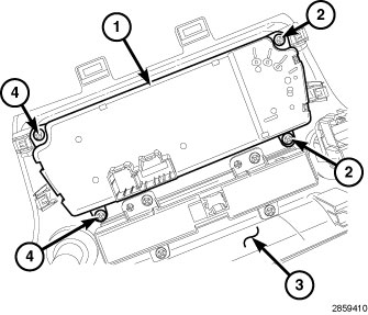
- Remove the instrument panel center bezel (3) and place it on a workbench (Refer to 23 - Body/Instrument Panel/BEZEL, Instrument Panel - Removal) .
-
Remove the four screws (2 and 4) that secure the A/C-heater control (1) to the back of the center bezel and remove the control.
INSTALLATION
INSTALLATION
| NOTE: |
Take the proper precautions to protect the front face of the center bezel from cosmetic damage while performing this procedure. |
|
| NOTE: |
ATC control shown. MTC control similar. |
- Position the A/C-heater control (1) onto the back of the center bezel (3).
- Install the four screws (2 and 4) that secure the A/C-heater control to the bezel. Tighten the screws to 2 N·m (17 in. lbs.).
- Install the center bezel (Refer to 23 - Body/Instrument Panel/BEZEL, Instrument Panel - Installation) .
-
Reconnect the negative battery cable.
NOTE: When installing a new A/C-heater control, or reinstalling the original control, the A/C-heater control will automatically run the Actuator Calibration function when the ignition switch is initially turned to ON. However, the Actuator Calibration function must be manually initiated using a scan tool if the A/C-heater control was previously installed in another vehicle.
-
If required, initiate the Actuator Calibration function using a scan tool (Refer to 28 - DTC-Based Diagnostics/HVAC - Standard Procedure)
.