CAMSHAFT, Engine
DESCRIPTION
DESCRIPTION
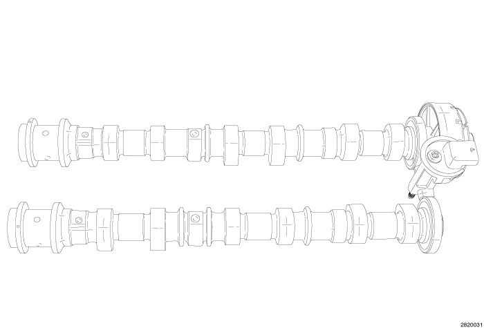 |
The 3.6L engine uses a Dual Over Head Camshaft (DOHC) configuration. The camshafts are a nodular cast iron design and have a pressed on magnetic timing wheel that is magnetic encoded. The two Camshaft Position (CMP) sensors are located between the timing wheels. Attached to the rear of the right exhaust camshaft is a centrifuge which is part of the crankcase ventilation system. The centrifuge is used to separate oil droplets from the crankcase gases before they enter the PCV valve. Four bearing journals are machined into the camshaft. Camshaft end play is controlled by two thrust walls that border the nose piece journal.
OPERATION
OPERATION
 |
| NOTE: |
RH camshafts shown, LH camshafts similar. |
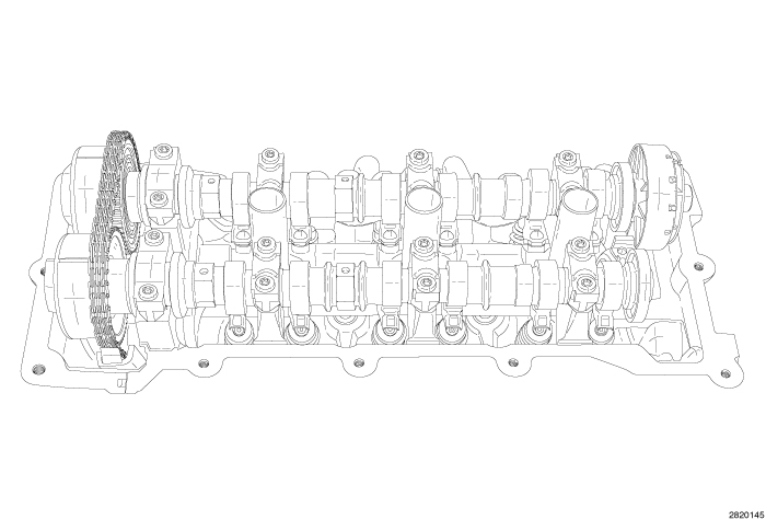
The camshaft has precisely machined (egg shaped) lobes to provide accurate valve timing and duration. The camshaft is driven by the crankshaft via drive sprockets and chains.
CAMSHAFT END PLAY
CAMSHAFT END PLAY
| NOTE: |
Right intake camshaft shown, other camshafts similar. |
-
Remove the cylinder
head cover (Refer to 09 - Engine/Cylinder
Head/COVER(S)
, Cylinder Head - Removal).
NOTE: Cylinder #1 or #4 must be used when checking for Top Dead Center (TDC).
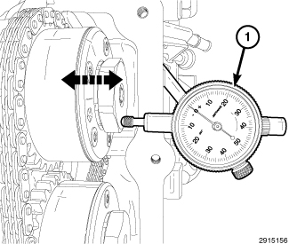
- Mount Dial Indicator Set C-3339A (1) to a stationary point at the front of the engine. Locate the probe perpendicular against the nose of the camshaft.
- Move the camshaft all the way to the rear of its travel.
- Zero the dial indicator.
-
Move the camshaft forward
to the limit of travel and read the dial indicator. Compare the measured
end play to the specification (Refer to 09 - Engine - Specifications)
.
LEFT
LEFT
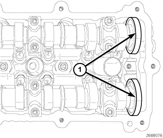 |
The magnetic timing wheels (1)
must not come in contact with magnets (pickup tools, trays, etc.)
or any other strong magnetic field. This will destroy the timing wheels
ability to correctly relay camshaft position to the camshaft position
sensor.
CAUTION:
When the timing chain is removed
and the cylinder heads are still installed, Do not forcefully rotate
the camshafts or crankshaft independently of each other. Severe valve
and/or piston damage can occur.
CAUTION:
DO NOT STAMP OR STRIKE THE CAMSHAFT
BEARING CAPS. SEVERE DAMAGE WILL OCCUR TO THE BEARING CAPS.
CAUTION:
-
Remove the upper intake
manifold, all ignition coils, all spark plugs and left cylinder head
cover (Refer to 09 - Engine/Cylinder
Head/COVER(S)
, Cylinder Head/Removal) .
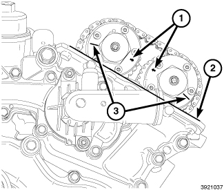
-
The left side
cam phaser SCRIBE
LINES (3) should face away from each other and the ARROWS (1) should
point toward each other and be parallel to the cylinder head cover
mounting surface (2). The number one cylinder piston is positioned
at top-dead-center on the exhaust stroke.
-
Mark the camshaft
phasers to the timing chain with a paint pen or equivalent.
NOTE: Graphic shows engine timing cover removed for clarity.
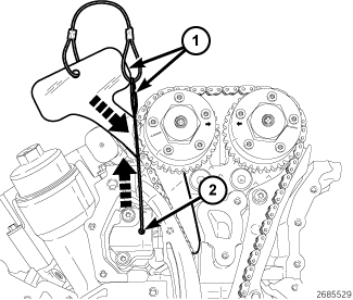
-
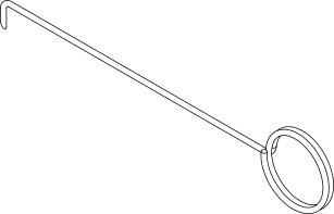
Using the
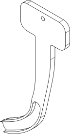
Pin 10200-3 (2), lift the pawl off of the rack (3). While holding the
pawl off of the rack, push
Holder, Timing Chain, Left Side 10200-1 (1) into place between the cylinder head and the cam chain
guide to force the rack and piston back into the tensioner body.
NOTE: The holder remains in place while the phasers are removed.
NOTE: Minor rotation of a camshaft (a few degrees) may be required when installing the LH Camshaft/Phaser Lock.
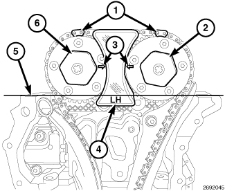
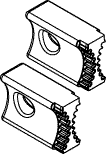
- Install the Locks, Camshaft/Phaser 10202 (4).
-
Remove the exhaust
oil control valve (2) and the intake oil control valve (6).
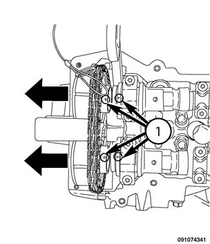
NOTE: The alignment marks located on the camshaft specifies the location of the drive pin in reference to the phaser alignment mark.
-
Using care.
Remove both the intake and exhaust oil control valves simultaneously.
NOTE: DO NOT REMOVE THE PHASER LOCK.
NOTE: Camshaft bearing caps should have been marked during engine manufacturing. For example, the number one exhaust camshaft bearing cap is marked “1E–>”. The caps should be installed with the notch forward.
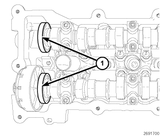
- Rotate the camshafts counterclockwise to position the alignment holes (1) approximately 30° before top-dead-center. This places the camshafts in the neutral position (no valve load).
-
Loosen the camshaft
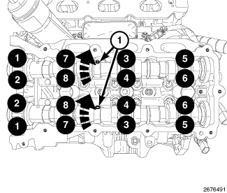
bearing cap bolts in the sequence shown.
NOTE: When the camshaft is removed the rocker arms may slide downward, mark the rocker arms before removing the camshaft.
-
Remove the camshaft
bearing caps and the camshafts.
RIGHT
RIGHT
 |
The magnetic timing wheels (1)
must not come in contact with magnets (pickup tools, trays, etc.)
or any other strong magnetic field. This will destroy the timing wheels
ability to correctly relay camshaft position to the camshaft position
sensor.
CAUTION:
When the timing chain is removed
and the cylinder heads are still installed, Do not forcefully rotate
the camshafts or crankshaft independently of each other. Severe valve
and/or piston damage can occur.
CAUTION:
DO NOT STAMP OR STRIKE THE CAMSHAFT
BEARING CAPS. SEVERE DAMAGE WILL OCCUR TO THE BEARING CAPS.
CAUTION:
 |
- Remove the upper intake manifold, all ignition coils, all spark plugs, right cylinder head cover (Refer to 09 - Engine/Cylinder Head/COVER(S) , Cylinder Head/Removal) .
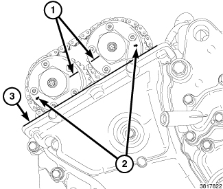
- The right side cam phaser ARROWS (2) should point away from each other and the SCRIBE LINES (1) should be parallel to the cylinder head cover mounting surface (3) when the right side number one cylinder piston is positioned at top-dead-center on the exhaust stroke.
-
Mark the camshaft
phasers to the timing chain with a paint pen or equivalent.
-
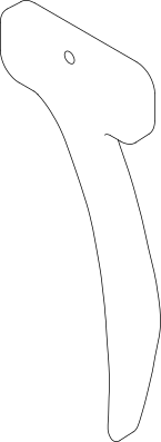
Use the timing
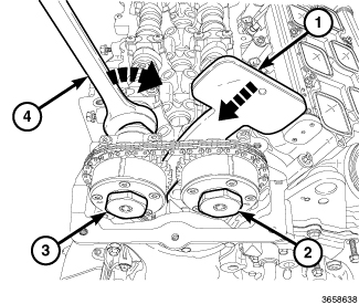
chain to compress the tensioner by slightly rotating the exhaust camshaft
clockwise (4). Insert the
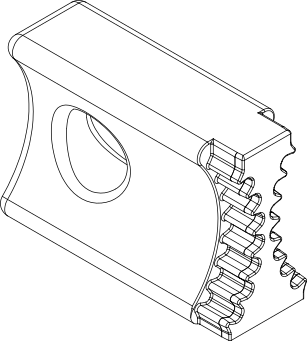
Holder, Timing Chain 10369 (1) into place between the cylinder head boss and the tensioner
arm to hold the tensioner in the compressed position. The Timing Chain
Holder remains in place while the phasers are removed.
NOTE: Minor rotation of a camshaft (a few degrees) may be required when installing the RH Camshaft/Phaser Lock.
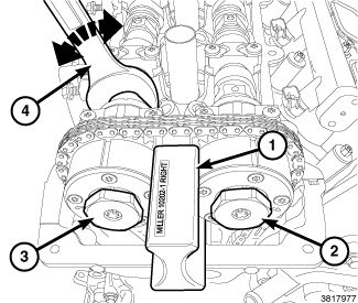
- Install Lock, Camshaft/Phaser, Right Side 10202-1 (1).
-
Remove both
the intake (2) and exhaust (3) oil control valves.
NOTE: Left side shown. Right side similar.
-
Using care.
Remove both the intake and exhaust oil control valves simultaneously.
NOTE: DO NOT REMOVE THE PHASER LOCK
-
Camshaft bearing caps
should have been marked during engine manufacturing. For example,
the number one exhaust camshaft bearing cap is marked “1E–>”. The
caps should be installed with the notch forward.
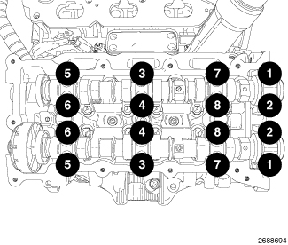
NOTE: Loosen the camshaft bearing cap bolts in the sequence shown.
NOTE: When the camshaft is removed the rocker arms may slide downward, mark the rocker arms before removing the camshaft.
-
Remove the camshaft
bearing caps and the camshafts.
INSPECTION
INSPECTION
 |
| NOTE: |
RH intake camshaft shown, other camshafts similar. |
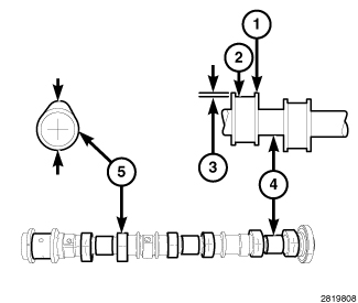
- Inspect camshaft bearing journals (4) for damage and binding. If journals are binding, check the cylinder head for damage. Also check cylinder head oil holes for clogging.
-
Check the surface of the cam lobes (5) for abnormal wear (3). Measure and compare the unworn area (1) to the worn area (2). Replace camshafts that are not within specification (Refer to 09 - Engine - Specifications)
.
LEFT
LEFT
|
The magnetic timing wheels (1)
must not come in contact with magnets (pickup tools, trays, etc.)
or any other strong magnetic field. This will destroy the timing wheels
ability to correctly relay camshaft position to the camshaft position
sensor.
CAUTION:
 |
-
Lubricate the camshaft
journals with clean engine oil.
CAUTION: Do not rotate the camshafts more than a few degrees independently of the crankshaft. Valve to piston contact could occur resulting in possible valve damage. If the camshafts need to be rotated more than a few degrees, first move the pistons away from the cylinder heads by rotating the crankshaft counterclockwise to a position 30° before-top-dead-center. Once the camshafts are returned to their top-dead-center position, rotate the crankshaft clockwise to return the crankshaft to top-dead-center.
- Install the left side camshaft(s) with the alignment holes (1) positioned approximately 30° before top-dead-center. This will place the camshafts at the neutral position (no valve load) easing the installation of the camshaft bearing caps. Caps are identified numerically (1 through 4), intake or exhaust (I or E) and should be installed from the front to the rear of the engine. All caps should be installed with the notch forward so that the stamped arrows (<) on the caps point toward the front of the engine.
- Verify the rocker arms are aligned to the cam lobe (Refer to 09 - Engine/Cylinder Head/ROCKER ARM, Valve/Installation) .
- Install the camshaft bearing caps and hand tighten the retaining bolts to 2 N·m (18 in. lbs.).
-
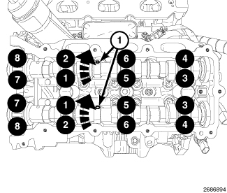
Tighten the bearing
cap retaining bolts in the sequence shown to 9.5 N·m (84 in. lbs.).
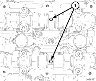
- Rotate the camshafts clockwise to top-dead-center by positioning the alignment holes (1) vertically.
-
Install the
timing chain tensioner holder.
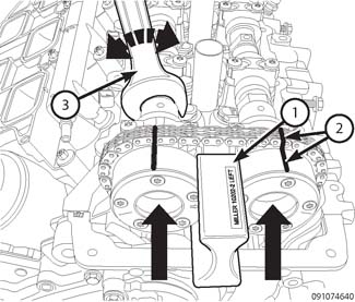
NOTE: Minor rotation of a camshaft (a few degrees) may be required when installing the LT Camshaft/Phasers to the camshaft alignment pins.
- Verify the cam phasers are aligned with the marks (2) made on the timing chain.
-
Install the
camshaft phasers onto the camshafts.
-
Using care,
slowly rotate the engine four revolutions to verify the valve to piston
clearance and camshaft phaser timing mark alignment (1).
- Install the cylinder head cover, spark plugs, ignition coils and the upper intake manifold (Refer to 09 - Engine/Cylinder Head/ASSEMBLY, Variable Valve Timing - Installation)
| NOTE: |
The Cam/Crank Variation
Relearn procedure must be performed using the scan tool anytime there
has been a repair/replacement made to a powertrain system, for example:
flywheel, valvetrain, camshaft and/or crankshaft sensors or components. |
RIGHT
RIGHT
|
The magnetic timing wheels (1)
must not come in contact with magnets (pickup tools, trays, etc.)
or any other strong magnetic field. This will destroy the timing wheels
ability to correctly relay camshaft position to the camshaft position
sensor.
CAUTION:
 |
-
Lubricate camshaft
journals with clean engine oil.
CAUTION: Do not rotate the camshafts more than a few degrees independently of the crankshaft. Valve to piston contact could occur resulting in possible valve damage. If the camshafts need to be rotated more than a few degrees, first move the pistons away from the cylinder heads by rotating the crankshaft counterclockwise to a position 30° before-top-dead-center. Once the camshafts are returned to their top-dead-center position, rotate the crankshaft clockwise to return the crankshaft to top-dead-center.
-
Install the right side
camshaft(s) at top-dead-center by positioning the alignment holes
(1) vertically. This will place the camshafts at the neutral position
(no valve load) easing the installation of the camshaft bearing caps.
NOTE: Caps are identified numerically (1 through 4), intake or exhaust (I or E) and should be installed from the front to the rear of the engine. All caps should be installed with the notch forward so that the stamped arrows (<) on the caps point toward the front of the engine.
- Install the camshaft bearing caps and hand tighten the retaining bolts to 2 N·m (18 in. lbs.).
- Verify the rocker arms are aligned to the cam lobe (Refer to 09 - Engine/Cylinder Head/ROCKER ARM, Valve/Installation) .
-
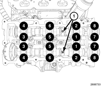
Tighten the bearing
cap retaining bolts in the sequence shown to 9.5 N·m (84 in. lbs.).
-
Verify the alignment
holes are vertical to the cylinder head surface.
NOTE: Minor rotation of a camshaft (a few degrees) may be required when installing the RT Camshaft/Phasers to the camshaft alignment pins.
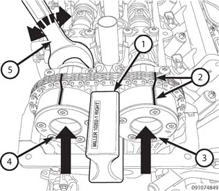
- Verify the cam phasers (3 and 4) are aligned to the marks (2) made on the timing chain.
- Install the phasers (3 and 4) onto the camshafts.
-
Install the
oil control valves. Tighten to 150 N·m (110 ft. lbs.).
-
Using care,
slowly rotate the engine four revolutions to verify the valve to piston
clearance and camshaft phaser timing mark alignment (1).
- Install the cylinder head cover, spark plugs, ignition coils and the upper intake manifold (Refer to 09 - Engine/Cylinder Head/ASSEMBLY, Variable Valve Timing - Installation)
| NOTE: |
The Cam/Crank Variation
Relearn procedure must be performed using the scan tool anytime there
has been a repair/replacement made to a powertrain system, for example:
flywheel, valvetrain, camshaft and/or crankshaft sensors or components. |