VALVES, Intake and Exhaust
DESCRIPTION
DESCRIPTION
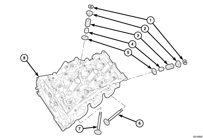 |
The intake valve (6) is made from a one piece forged heat resistant (martensitic) steel. The exhaust valve (7) is a two piece construction with a forged (austenitic) head welded to the (martensitic) stem. Both valves have a nitrided surface treatment to prevent scuffing except at the tip and lock grooves. The four valves per cylinder are actuated by roller rocker arms, which pivot on stationary lash adjusters. All valves use three bead lock keepers (1) to retain springs (3) and to promote valve rotation.
REFACING INTAKE AND EXHAUST VALVES
REFACING INTAKE AND EXHAUST VALVES
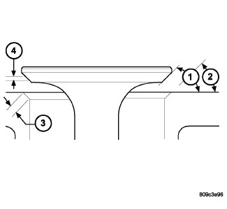 |
1 - SEAT WIDTH
2 - FACE ANGLE
3 - SEAT ANGLE
4 - SEAT CONTACT AREA
The intake and exhaust valves have a 45.25 ± 0.25 degree face angle (1). The valve seats (2) have a 44.75 ± 0.25 degree face angle.
VALVES
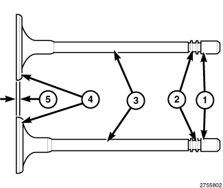 |
Inspect the remaining margin (5) after the valves are refaced (Refer to 09 - Engine - Specifications)
.
VALVE SEATS
|
| NOTE: |
When refacing the valve seats, it is important that the correct size valve guide pilot be used for the reseating stones. A true and complete surface must be obtained. |
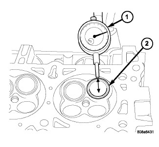
- Measure the concentricity of the valve seat using a dial indicator. Total runout should not exceed 0.050 mm (0.002 inch.) total indicator reading.
-
Inspect the valve seat (3) with Prussian blue to determine where the valve contacts the seat. To do this, coat the valve seat (3) LIGHTLY with Prussian blue then set the valve in place. Rotate the valve with light pressure. If the blue is transferred to the center of the valve face (4), contact is satisfactory. If the blue is transferred to the top edge of the valve face, then lower the valve seat with a 15 degree stone. If the blue is transferred to the bottom edge of the valve face, then raise the valve seat with a 65 degree stone.
NOTE: Valve seats which are worn or burned can be reworked, provided that the correct angle and seat width are maintained. Otherwise the cylinder head must be replaced.
-
When the seat is properly positioned the width of the intake seat should be 1.0 - 1.2 mm (0.04 - 0.05 in.) and the exhaust seats should be 1.41 - 1.61 mm (0.055 - 0.063 in.).
VALVE AND SPRING INSTALLED HEIGHT
 |
-
Coat the valve stems (2) with clean engine oil and install the valves into the cylinder head.
NOTE: If the valves are being reused, reassemble them into their original locations.
-
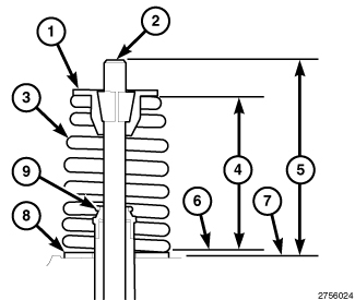
If the valves or valve seats have been refinished, check the valve tip height (5). If the valve tip height (5) exceeds the specification, grind the valve tip until it is within specification (Refer to 09 - Engine - Specifications)
. Make sure the measurement is taken from the cylinder head surface (7) to the top of the valve stem (2).
-
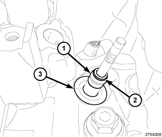
If removed, install the spring seat (3) and valve guide seal (1) over the valve guide (Refer to 09 - Engine/Cylinder Head/SEAL(S)
, Valve Guide - Installation).
NOTE: Ensure that the garter spring (2) is intact around the top of the valve guide seal (1). Number 5 cylinder exhaust valve guide seal shown, all other valves similar.
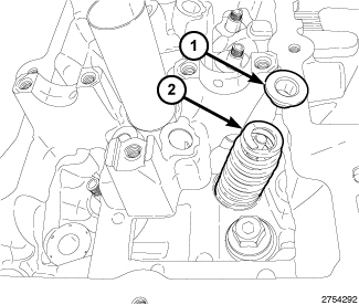
NOTE: If the valve springs are being reused, reassemble them into their original locations. Number 5 cylinder exhaust valve spring shown, all other valves similar.
-
Install the valve spring (2) and valve spring retainer (1).
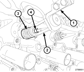
NOTE: Number 3 cylinder intake valve spring compression shown, all other valves similar.
-
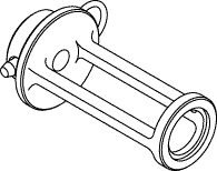
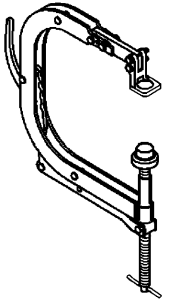
Compress valve springs (3) with the Valve Spring Compressor Adapter 10224 (2) mounted in the Valve Spring Compressor C-3422-D (1). Install the retaining locks (4) and release the valve spring compression.
-
If the valves or valve seats have been refinished, check the installed height of the valve springs (4). If the installed valve spring height (4) is greater than 40.0 mm (1.575 in.), install a second spring seat (8) in the head counterbore under the valve spring seat (8) to bring the spring height back within specification. Make sure the measurement is taken from the top of spring seat (6) to the bottom surface of spring retainer (1).
REMOVAL
REMOVAL
|
-
Remove the cylinder head(s) (Refer to 09 - Engine/Cylinder Head - Removal)
.
NOTE: If the springs are to be reused, identify their positions so that they can be reassembled into their original locations. Number 5 cylinder exhaust valve spring shown, all other valve springs similar.
-
Remove the valve spring(s) (2) (Refer to 09 - Engine/Cylinder Head/SPRING(S)
, Valve - Removal).
CAUTION: Before removing the valves, remove any burrs from the valve stem retainer lock grooves (2) and stem tip (1) to prevent damage to the valve guides.
-
Remove the valve(s) (3). Identify each valve to ensure installation in the original location.
-
If required, remove the valve guide seal (1) and spring seat (3) (Refer to 09 - Engine/Cylinder Head/SEAL(S)
, Valve Guide - Removal).
INSPECTION
INSPECTION
Valves
|
- Clean and inspect the valves thoroughly. Replace burned, warped and cracked valves.
- Inspect the retainer lock grooves for wear or damage (2).
- Inspect the valve face (4) for for wear and pitting.
-
Measure the valve stems (3) and margins (5) for wear (Refer to 09 - Engine - Specifications)
.
Valve Guides
 |
- Remove carbon and varnish deposits from inside of the valve guides with a reliable guide cleaner.
- Measure valve stem-to-guide clearance as follows:
- Install the valve (2) into the cylinder head so that it is 15 mm (0.590 inch.) off of the valve seat. A small piece of hose may be used to hold the valve in place.
- Attach the Dial Indicator Set C-3339A (1) to the cylinder head and set it at a right angle to the valve stem being measured.
- Move the valve to and from the indicator. Compare this reading to the specification (Refer to 09 - Engine - Specifications) .
| NOTE: |
If stem-to-guide clearance exceeds specifications, you must measure the valve stem. If the valve stem is within specification or if the valve guide is loose in the cylinder head, replace the cylinder head. |
INSTALLATION
INSTALLATION
|
-
Coat the valve stems (2) with clean engine oil and install the valves into the cylinder head.
NOTE: If the valves are being reused, reassemble them into their original locations.
-
If the valves or valve seats have been refinished, check the valve tip height (5). If the valve tip height (5) exceeds the specification, grind the valve tip until it is within specification (Refer to 09 - Engine - Specifications)
. Make sure the measurement is taken from the cylinder head surface (7) to the top of the valve stem (2).
-
If removed, install the spring seat (3) and valve guide seal (1) over the valve guide (Refer to 09 - Engine/Cylinder Head/SEAL(S)
, Valve Guide - Installation).
NOTE: Ensure that the garter spring (2) is intact around the top of the valve guide seal (1). Number 5 cylinder exhaust valve guide seal shown, all other valves similar.
-
Install the valve spring(s) (2) (Refer to 09 - Engine/Cylinder Head/SPRING(S)
, Valve - Installation).
NOTE: Reassemble the valves springs into their original locations. If the valves or valve seats have been refinished, verify that the valve spring installed height is within specification (Refer to 09 - Engine - Specifications) . Number 5 cylinder exhaust valve spring shown, all other valves springs similar.
-
Install the cylinder head(s) (Refer to 09 - Engine/Cylinder Head - Installation)