BEARING(S), Connecting Rod
Connecting Rod Bearing Fitting
Connecting Rod Bearing Fitting
Bearing oil clearance can also be determined by using Plastigage or equivalent (Refer to 09 - Engine/Engine Block - Standard Procedure)
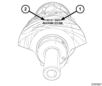 |
The connecting rod bearings are “select fit” to achieve proper oil clearance. Connecting rod bearing journal diameter grade markings (2) are stamped into the front crankshaft counterweight. These marks are read from left to right, corresponding with journal number 1, 2, 3, 4, 5, 6. Select the bearing size that corresponds to the crankshaft markings for each rod bearing journal.
Connecting rod bearing journal diameter grade markings correspond to specific journal diameters. The chart below identifies the three crankshaft grade markings and their associated journal diameters.
|
Crankshaft Marking |
Journal Size mm (in.) |
|---|---|
|
1 |
58.9910 - 58.9969 mm (2.3225 - 2.3227 in.) |
|
2 |
58.9970 - 59.0029 mm (2.3227 - 2.3229 in.) |
|
3 |
59.0030 - 59.0090 mm (2.3229 - 2.3232 in.) |
 |
| NOTE: |
Install the rod bearings in pairs. Do not mix sizes or use a new bearing half with an old bearing half. |
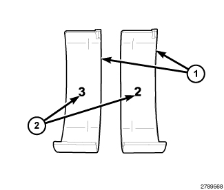
The connecting rod bearing shells (1) are marked with the bearing size (2) on the bearing lining surface. The bearings are available in three different sizes in order to achieve the desired oil clearance.
Rod bearing shells are available in three sizes. The chart below identifies the three bearing sizes.
|
Bearing Marking |
Size mm (in.) |
|---|---|
|
1 |
1.583 - 1.580 mm (0.0623 - 0.0622 in.) |
|
2 |
1.580 - 1.577 mm (0.0622 - 0.0621 in.) |
|
3 |
1.577 - 1.574 mm (0.0621 - 0.0620 in.) |
Connecting Rod Bearing Replacement
Connecting Rod Bearing Replacement
|
The connecting rod bearings (1) are serviced in-vehicle. They must be replaced one-at-a-time in order to prevent the pistons from contacting the valves. The connecting rod bearings are “select fit” to achieve proper oil clearances (Refer to 09 - Engine/Engine Block/BEARING(S)
, Connecting Rod - Standard Procedure).
 |
- Disconnect and isolate the negative battery cable.
- Remove the spark plugs (Refer to 08 - Electrical/8I - Ignition Control/SPARK PLUG - Removal)
- Remove the oil pan, oil pump pick-up and engine oil pump (Refer to 09 - Engine/Lubrication/PUMP, Engine Oil - Removal)
-
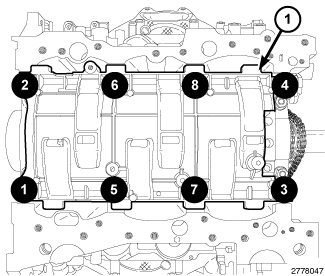
Remove the eight main bearing cap bolts from the windage tray in the sequence shown and remove the windage tray (1).
CAUTION: DO NOT use a number stamp or a punch to mark connecting rods or caps, as damage to connecting rods could occur
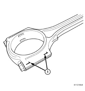
NOTE: Connecting rods and bearing caps are not interchangeable and should be marked before removing to ensure correct reassembly.
-
Mark connecting rod and bearing cap positions (1) using a permanent ink marker or scribe tool.
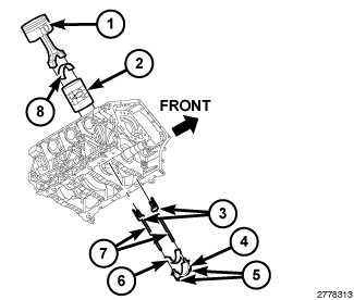
NOTE: Typical V6 engine configuration shown.
CAUTION: Replace only one connecting rod bearing at a time while all other connecting rod bearing caps remain properly tightened. If all connecting rod bearing caps are removed, crankshaft rotation will result in valve and/or piston damage.
CAUTION: Care must be taken not to damage the fractured rod and cap joint face surfaces, as engine damage may occur.
- Remove the connecting rod cap bolts (5) and the connecting rod cap (4). Discard the cap bolts.
-
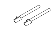
Remove the plastic guide plates (3) from the Guide Pins 8189 (7) and install the Guide Pins to the connecting rod being removed.
CAUTION: Care must be taken not to nick crankshaft journals, as engine damage may occur.
- Rotate the crankshaft away from the connecting rod and remove the bearing shell.
- If required, select and fit new bearings to the connecting rod (Refer to 09 - Engine/Engine Block/BEARING(S) , Connecting Rod - Standard Procedure)
- Install the bearing shell (8) on the connecting rod with the tang inserted into the machined groove in the rod. Lubricate the bearing surface with clean engine oil.
-
Rotate the crankshaft while guiding the connecting rod into position over the rod journal.
CAUTION: The connecting rod bolts must not be reused. Always replace the connecting rod bolts whenever they are loosened or removed.
-
Install the bearing shell (6) on the connecting rod cap (4) with the tang inserted into the machined groove in the cap. Lubricate the bearing surface with clean engine oil.
NOTE: Do not lubricate the threads of the connecting rod cap bolts (5).
- Install the connecting rod cap and bearing with the tang on the same side as the rod. Tighten the the NEW connecting rod cap bolts (5) to 20 N·m (15 ft. lbs.) plus 90°.
- If required, check the connecting rod side clearance (Refer to 09 - Engine/Engine Block/ROD, Piston and Connecting - Standard Procedure)
-
Repeat the previous steps for each connecting rod bearing being replaced.
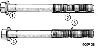
CAUTION: The main bearing cap bolts are tightened using a torque plus angle procedure. The bolts must be examined BEFORE reuse. If the threads are necked down the bolts must be replaced.
-
Check the main bearing cap bolts for necking by holding a scale or straight edge against the threads. If all the threads do not contact the scale (2) the bolt must be replaced.
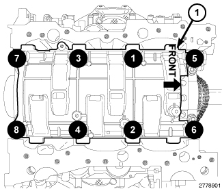
- Install the windage tray with eight main bearing cap bolts. Tighten the bolts in the sequence shown to 21 N·m (16 ft. lbs.) plus 90°.
- Install the engine oil pump, oil pump pick-up and oil pan (Refer to 09 - Engine/Lubrication/PUMP, Engine Oil - Installation)
- Install the spark plugs and ignition coils (Refer to 08 - Electrical/8I - Ignition Control/SPARK PLUG - Installation)
- If removed, install the oil filter and fill the engine crankcase with the proper oil to the correct level (Refer to 09 - Engine/Lubrication/OIL - Standard Procedure)
- Connect the negative battery cable and tighten nut to 5 N·m (45 in. lbs.).
-
Operate the engine until it reaches normal operating temperature.