BEARING(S), Crankshaft, Main
Main Bearing Fitting
Main Bearing Fitting
| NOTE: |
Crankshaft thrust washers are not selectable and are only available in a single thickness. |
Bearing oil clearance can also be determined by using Plastigage or equivalent (Refer to 09 - Engine/Engine Block - Standard Procedure)
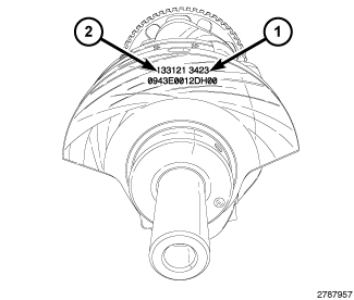 |
The upper and lower main bearings are “select fit” to achieve proper
oil clearances. Crankshaft main bearing journal diameter grade markings
(1) are stamped into the front crankshaft counterweight. These marks
are read from left to right, corresponding with journal number 1,
2, 3, 4.
Crankshaft main bearing journal diameter grade markings correspond to specific journal diameters. The chart below identifies the five crankshaft grade markings and their associated journal diameters.
|
Crankshaft Marking |
Journal Size mm (in.) |
|---|---|
|
1 |
71.9870 - 71.9905 mm (2.8341 - 2.8343 in.) |
|
2 |
71.9906 - 71.9941 mm (2.8343 - 2.8344 in.) |
|
3 |
71.9942 - 71.9977 mm (2.8344 - 2.8345 in.) |
|
4 |
71.9978 - 72.0013 mm (2.8346 - 2.8347 in.) |
|
5 |
72.0014 - 72.0050 mm (2.8347 - 2.8348 in.) |
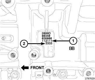 |
Engine block main bearing journal diameter grade markings (2) are
stamped into the left side of the engine block. These marks are read
from left to right, corresponding with journal number 1, 2, 3, 4.
Engine block main bearing journal grade markings correspond to specific journal diameters. The chart below identifies the five engine block grade markings and their associated journal diameters.
|
Engine Block Marking |
Journal Size mm (in.) |
|---|---|
|
1 |
77.0055 - 77.0090 mm (3.0317 - 3.0318 in.) |
|
2 |
77.0019 - 77.0054 mm (3.0316 - 3.0317 in.) |
|
3 |
76.9983 - 77.0018 mm (3.0314 - 3.0316 in.) |
|
4 |
76.9947 - 76.9982 mm (3.0313 - 3.0314 in.) |
|
5 |
76.9910 - 76.9946 mm (3.0311 - 3.0313 in.) |
For upper and lower main bearing selection, obtain the grade identification marks from the crankshaft and engine block. Main bearings are available in five sizes. Upper and lower sizes can be mixed on a journal in order to achieve the desired oil clearance. The chart below identifies the five sizes available and how they should be selected based on crankshaft and engine block grade markings.
|
Engine Block Marking |
Crankshaft Marking |
||||
|
1 |
2 |
3 |
4 |
5 |
|
|
1 |
1/1 |
1/2 |
2/2 |
2/3 |
3/3 |
|
2 |
1/2 |
2/2 |
2/3 |
3/3 |
3/4 |
|
3 |
2/2 |
2/3 |
3/3 |
3/4 |
4/4 |
|
4 |
2/3 |
3/3 |
3/4 |
4/4 |
4/5 |
|
5 |
3/3 |
3/4 |
4/4 |
4/5 |
5/5 |
|
UPPER/LOWER Main Bearings to Achieve 0.024 - 0.050 mm (0.0009 - 0.0020 in.) Oil Clearance |
|||||
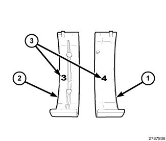 |
The upper main bearing shell (2) and lower main bearing shell (1)
are marked with the bearing size (3) on the bearing lining surface.
The upper and lower bearings are available in five different sizes
and can be mixed on a journal in order to achieve the proper oil clearance.
Upper and lower main bearing shells are available in five sizes. The chart below identifies the five bearing sizes.
|
Bearing Marking |
Size mm (in.) |
|---|---|
|
1 |
2.4951 - 2.4987 mm (0.0982 - 0.0984 in.) |
|
2 |
2.4915 - 2.4951 mm (0.0981 - 0.0982 in.) |
|
3 |
2.4879 - 2.4915 mm (0.0979 - 0.0981 in.) |
|
4 |
2.4843 - 2.4879 mm (0.0978 - 0.0979 in.) |
|
5 |
2.4807 - 2.4843 mm (0.0977 - 0.0978 in.) |
STANDARD PROCEDURE - MAIN BEARING REPLACEMENT
STANDARD PROCEDURE - MAIN BEARING REPLACEMENT
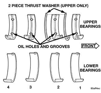 |
The main bearings are serviced in-vehicle. They must be replaced one-at-a-time in order to properly support the crankshaft. The upper and lower main bearing shells are NOT interchangeable. The upper and lower main bearings are “select fit” to achieve proper oil clearances (Refer to 09 - Engine/Engine Block/BEARING(S)
, Crankshaft - Standard Procedure).
 |
- Disconnect and isolate the negative battery cable.
-
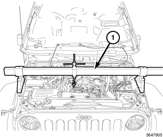
Position
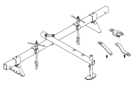
Fixture, Driveline Support 8534B (1) over the engine bay.
-
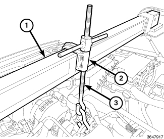
Install Adapters 8534-11(3) and 8534-13 (2) between the Engine Support Fixture 8534B (1) and the engine front cover. Carefully lift the engine to remove weight from both right and left engine mount isolators.
-
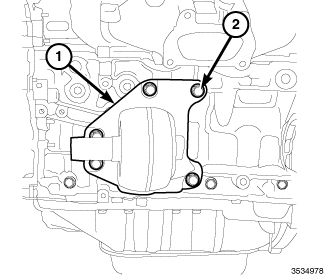
Remove the left engine mount isolator (1) (Refer to 09 - Engine/Engine Mounting/INSULATOR, Engine Mount - Removal)
.
-
Remove the right engine mount isolator (1) (Refer to 09 - Engine/Engine Mounting/INSULATOR, Engine Mount - Removal)
.
- Remove the oil pan, oil pump pick-up and engine oil pump (Refer to 09 - Engine/Lubrication/PUMP, Engine Oil - Removal)
-
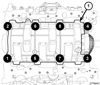
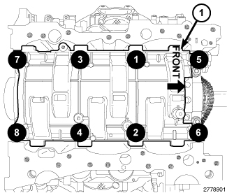
Remove the eight main bearing cap bolts from the windage tray in the sequence shown and remove the windage tray (1).
NOTE: Typical V6 engine configuration shown.
-
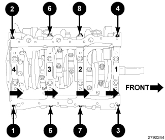
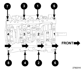
Remove the eight main bearing tie bolts in the sequence shown.
CAUTION: DO NOT use a number stamp or a punch to mark main bearing caps, as damage to main bearings could occur.
NOTE: Main bearing caps are not interchangeable and are marked to insure correct assembly.
-
Mark the main bearing cap positions using a permanent ink marker or a scribe tool.
NOTE: Typical V6 engine configuration shown.
CAUTION: Replace only one main bearing at a time while all other main bearing caps remain properly tightened. If all main bearing caps are removed, the weight of the unsupported crankshaft will damage the crankshaft oil seals.
NOTE: Replace the main bearings in the following order; 2, 3, 1, 4.
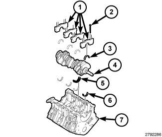
- Remove the two cap bolts (2) and remove the main bearing cap (1).
- When removing the No. 2 bearing cap, also remove the thrust washers (5).
- Slide the upper main bearing half (6) out from between the crankshaft and the engine block.
- If required, select fit new main bearings to the engine block (Refer to 09 - Engine/Engine Block/BEARING(S) , Crankshaft - Standard Procedure)
-
Lubricate the upper main bearing half (6) with clean engine oil and slide the bearing into position.
.
NOTE: Typical V6 engine configuration shown.
-
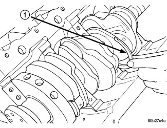
When installing thrust washers (1) at the No. 2 main bearing location, use the following procedure:
- Move the crankshaft forward to the limit of travel. Lubricate and install the front thrust washer (1) by rolling the washer onto the machined shelf between the No. 2 upper main bulk head and crankshaft thrust surface.
-
Move the crankshaft rearward to the limit of travel. Lubricate and install the rear thrust washer by rolling the washer onto the machined shelf between the No. 2 upper main bulk head and crankshaft thrust surface.
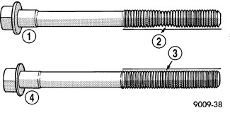
CAUTION: The main bearing cap bolts are tightened using a torque plus angle procedure. The bolts must be examined BEFORE reuse. If the threads are necked down the bolts must be replaced.
-
Check the main bearing cap bolts for necking by holding a scale or straight edge against the threads. If all the threads do not contact the scale (2) the bolt must be replaced.
NOTE: Typical V6 engine configuration shown.
- Lubricate and install the lower bearing half (3) onto the main cap (1).
- Install the main bearing cap (1) with two inner main bearing cap bolts (2) tightened to 20 N·m (15 ft. lbs.) plus 90°.
- Repeat the previous steps for main bearings 3, 1 and 4.
-
Measure crankshaft end play (Refer to 09 - Engine/Engine Block/CRANKSHAFT - Standard Procedure)
-
Install the windage tray with eight main bearing cap bolts. Tighten the bolts in the sequence shown to 21 N·m (16 ft. lbs.) plus 90°.
NOTE: Typical V6 engine configuration shown.
- Install the eight main bearing tie bolts. Tighten the bolts in the sequence shown to 28 N·m (21 ft. lbs.).
-
Install the engine oil pump, oil pump pick-up and oil pan (Refer to 09 - Engine/Lubrication/PUMP, Engine Oil - Installation)
-
Install the left engine mount isolator (1) (Refer to 09 - Engine/Engine Mounting/INSULATOR, Engine Mount - Installation)
.
- Install the right engine mount isolator (1) (Refer to 09 - Engine/Engine Mounting/INSULATOR, Engine Mount - Installation) .
- If removed, install the oil filter and fill the engine crankcase with the proper oil to the correct level (Refer to 09 - Engine/Lubrication/OIL - Standard Procedure)
- Connect the negative battery cable and tighten nut to 5 N·m (45 in. lbs.).
-
Operate the engine until it reaches normal operating temperature.