CRANKSHAFT
DESCRIPTION
DESCRIPTION
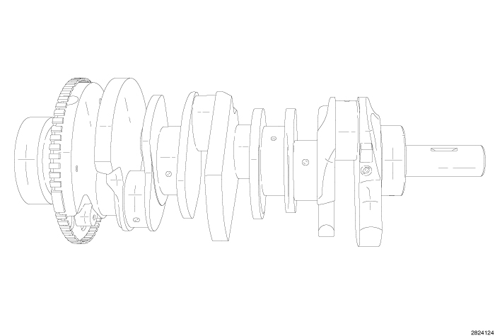 |
The crankshaft is a cast design and is constructed using ductile iron. The crankshaft is a three throw split pin design with counterweights for balancing purposes. The main journals are crossed drilled for rod bearing lubrication. The crankshaft is supported by four select fit main bearings with number 2 serving as the thrust washer location. The rear counterweight has provisions for crankshaft position sensor target wheel mounting. Both the front and rear seals are a single piece design and are mounted to the timing cover and cylinder block.
STANDARD PROCEDURE - END PLAY
STANDARD PROCEDURE - END PLAY
 |
| NOTE: |
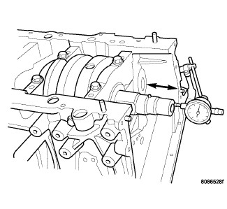
Typical V6 engine shown. |
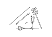
- Mount Dial Indicator Set C-3339A to a stationary point at the front of the engine. Locate the probe perpendicular against the nose of the crankshaft.
- Move the crankshaft all the way to the rear of its travel.
- Zero the dial indicator.
- Move the crankshaft forward to the limit of travel and read the dial indicator. Compare the measured end play to the specification (Refer to 09 - Engine - Specifications) .
| NOTE: |
Crankshaft thrust washers are not selectable and are only available in a single thickness. |
REMOVAL
REMOVAL
 |
| NOTE: |
To remove the crankshaft from the engine, the engine must be removed from the vehicle. |
-
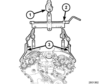
Remove the engine (Refer to 09 - Engine - Removal)
- Remove the cylinder head covers, spark plugs, upper oil pan, engine timing cover, timing chain and sprockets (Refer to 09 - Engine/Valve Timing/CHAIN and SPROCKETS, Timing - Removal)
- Remove the flexplate and the rear crankshaft oil seal (Refer to 09 - Engine/Engine Block/SEAL, Crankshaft Oil - Removal)
- Remove the oil pump pick-up and engine oil pump (Refer to 09 - Engine/Lubrication/PUMP, Engine Oil - Removal)
-
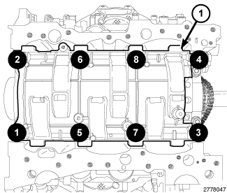
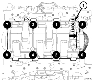
Remove the eight main bearing cap bolts from the windage tray in the sequence shown and remove the windage tray (1).
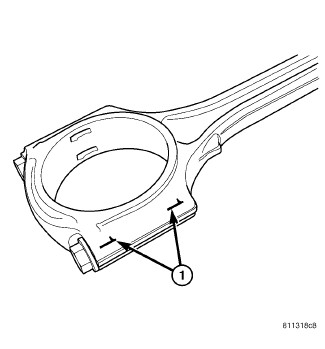
CAUTION: DO NOT use a number stamp or a punch to mark connecting rods or caps, as damage to connecting rods could occur
NOTE: Connecting rods and bearing caps are not interchangeable and should be marked before removing to ensure correct reassembly.
-
Mark connecting rod and bearing cap positions (1) using a permanent ink marker or scribe tool.
NOTE: Typical V6 engine configuration shown.
CAUTION: Care must be taken not to damage the fractured rod and cap joint face surfaces, as engine damage may occur.
-
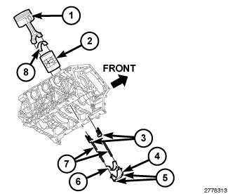
Remove the connecting rod cap bolts (5) and the connecting rod caps (4). Discard the cap bolts.
CAUTION: Care must be taken not to nick crankshaft journals, as engine damage may occur.
-
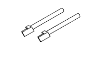
Remove the plastic guide plates (3) from the Guide Pins 8189 (7) and install the Guide Pins to the connecting rod.
CAUTION: Avoid contact with the piston oil cooler jet(s). Positioning of the oil cooler jet(s) is critical for proper engine operation.
-
Push the connecting rod and piston into the cylinder until the connecting rod is clear of the crankshaft journal. Remove the guide pins. Repeat this procedure at each cylinder until all of the connecting rods are clear of the crankshaft.
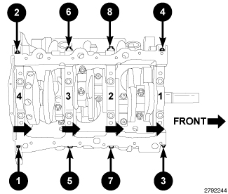
Remove the main bearing cross bolts in the sequence shown.NOTE: Typical V6 engine configuration shown.
CAUTION: DO NOT use a number stamp or a punch to mark main bearing caps, as damage to main bearings could occur.
NOTE: Main bearing caps are not interchangeable and are marked to insure correct assembly.
-
Mark the main bearing cap positions using a permanent ink marker or a scribe tool.
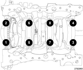
-
Remove the eight main bearing cap bolts in the sequence shown and remove the main bearing caps.
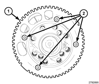
CAUTION: Do not rest the crankshaft on the target wheel (1). Damaged or bent target wheel teeth will destroy the target wheels ability to correctly relay crankshaft position to the crankshaft position sensor.
- Remove the crankshaft from the engine block.
-
If required, remove the four bolts (2) and the target wheel (1). Discard the four bolts.
INSPECTION
INSPECTION
 |
| NOTE: |
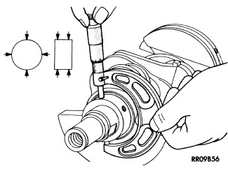
Typical crankshaft journal measurements shown. |
- Clean the oil off the bearing journals.
- Determine the maximum diameter of the journals with a micrometer. Measure at two locations 90° apart at each end of the journals.
- Compare the measured rod journal diameter to the crankshaft connecting rod bearing journal diameter grade marking chart (Refer to 09 - Engine/Engine Block/BEARING(S) , Connecting Rod - Standard Procedure)Select the bearing size that corresponds to the crankshaft markings for each rod bearing journal that will provide the proper oil clearance.
- Compare the measured main bearing journal diameter to the crankshaft main bearing journal diameter grade marking chart (Refer to 09 - Engine/Engine Block/BEARING(S) , Crankshaft - Standard Procedure)Obtain the main bearing journal grade identification marks from the engine block and select the upper and lower main bearing sizes that will provide the proper oil clearance.
- For connecting rod journals, verify that the maximum taper and maximum out of round are within specifications (Refer to 09 - Engine - Specifications) .
-
For main bearing journals, verify that the maximum taper and maximum out of round are within specifications (Refer to 09 - Engine - Specifications)
.
INSTALLATION
INSTALLATION
|
- If required, select and fit new crankshaft main bearings to the engine block (Refer to 09 - Engine/Engine Block/BEARING(S) , Crankshaft - Standard Procedure)
- If required, select and fit new bearings to the connecting rod (Refer to 09 - Engine/Engine Block/BEARING(S) , Connecting Rod - Standard Procedure)
-
If removed, install the target wheel (1) to the crankshaft with four new bolts (2). Ensure the threaded holes in the crankshaft are free of residual thread lock adhesive. Tighten the bolts to 10 N·m (89 in. lbs.).
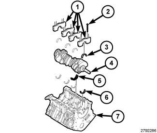
NOTE: Typical V6 engine configuration shown.
-
If removed, lubricate and install the upper main bearing halves (6) into the engine block (7).
CAUTION: When installing the crankshaft, use care not to damage bearing surfaces on the crankshaft.
-
Install the crankshaft (4) into the engine block (7).
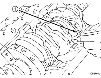
NOTE: Typical V6 engine configuration shown.
-
Installing thrust washers (1) at the No. 2 main bearing location, using the following procedure:
- Move the crankshaft forward to the limit of travel. Lubricate and install the front thrust washer (1) by rolling the washer onto the machined shelf between the No. 2 upper main bulk head and crankshaft thrust surface.
-
Move the crankshaft rearward to the limit of travel. Lubricate and install the rear thrust washer by rolling the washer onto the machined shelf between the No. 2 upper main bulk head and crankshaft thrust surface.
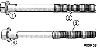
CAUTION: The main bearing cap bolts are tightened using a torque plus angle procedure. The bolts must be examined BEFORE reuse. If the threads are necked down the bolts must be replaced.
-
Check the main bearing cap bolts for necking by holding a scale or straight edge against the threads. If all the threads do not contact the scale (2) the bolt must be replaced.
NOTE: Typical V6 engine configuration shown.
- If removed, lubricate and install the lower main bearing halves (3) onto the main caps (1).
-
Install the main bearing caps (1) with two inner main bearing cap bolts (2).
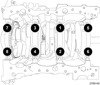
- Tighten the inner main bearing cap bolts in the sequence shown to 20 N·m (15 ft. lbs.) plus 90°.
-
Measure crankshaft end play (Refer to 09 - Engine/Engine Block/CRANKSHAFT - Standard Procedure)
NOTE: Typical V6 engine configuration shown.
-
If removed, install the bearing shell (8) on the connecting rod with the tang inserted into the machined groove in the rod. Lubricate the bearing surface with clean engine oil.
CAUTION: Care must be taken not to nick crankshaft journals, as engine damage may occur.
-
Remove the plastic guide plates (3) from the Guide Pins 8189 (7) and install the Guide Pins to the connecting rod.
CAUTION: Avoid contact with the piston oil cooler jet(s). Positioning of the oil cooler jet(s) is critical for proper engine operation.
-
Pull the connecting rod and piston toward the crankshaft until the connecting rod is seated on the crankshaft journal. Remove the guide pins.
CAUTION: The connecting rod bolts must not be reused. Always replace the connecting rod bolts whenever they are loosened or removed.
-
If removed, install the bearing shell (6) on the connecting rod cap (4) with the tang inserted into the machined groove in the cap. Lubricate the bearing surface with clean engine oil.
NOTE: Do not lubricate the threads of the connecting rod cap bolts (5).
- Install the connecting rod cap and bearing with the tang on the same side as the rod. Tighten the the NEW connecting rod cap bolts (5) to 20 N·m (15 ft. lbs.) plus 90°.
- If required, check the connecting rod side clearance (Refer to 09 - Engine/Engine Block/ROD, Piston and Connecting - Standard Procedure)
-
Repeat the previous steps for the remaining connecting rods.
-
Install the windage tray (1) with eight main bearing cap bolts. Tighten the bolts in the sequence shown to 21 N·m (16 ft. lbs.) plus 90°.
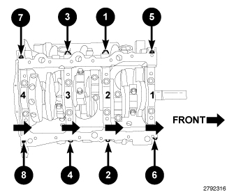
NOTE: Typical V6 engine configuration shown.
- Install the eight main bearing tie bolts. Tighten the bolts in the sequence shown to 28 N·m (21 ft. lbs.).
- Install the engine oil pump and oil pump pick-up (Refer to 09 - Engine/Lubrication/PUMP, Engine Oil - Installation)
- Install the rear crankshaft oil seal and flexplate (Refer to 09 - Engine/Engine Block/SEAL, Crankshaft Oil - Installation)
-
Install the timing chain and sprockets, engine timing cover, oil pans, spark plugs and cylinder head covers (Refer to 09 - Engine/Valve Timing/CHAIN and SPROCKETS, Timing - Installation)
- Install the engine (Refer to 09 - Engine - Installation)
- If removed, install the oil filter and fill the engine crankcase with the proper oil to the correct level (Refer to 09 - Engine/Lubrication/OIL - Standard Procedure)
- Connect the negative battery cable and tighten nut to 5 N·m (45 in. lbs.).
- Fill the cooling system (Refer to 07 - Cooling - Standard Procedure) .
- Operate the engine until it reaches normal operating temperature. Check cooling system for correct fluid level (Refer to 07 - Cooling - Standard Procedure)
| NOTE: |
The Cam/Crank Variation Relearn procedure must be performed using the scan tool anytime there has been a repair/replacement made to a powertrain system, for example: flywheel, valvetrain, camshaft and/or crankshaft sensors or components. |