MODULE, Balance Shaft
DESCRIPTION
DESCRIPTION
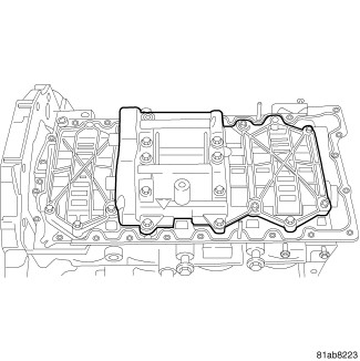 |
The balance shaft is gear-driven and is used to counteract engine vibration and roughness. The balance shaft assembly includes balancers on two shafts. It is only serviced as an assembly. Balance shafts must be timed to the crankshaft.
REMOVAL
REMOVAL
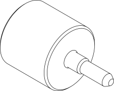
Special Tools: Click to display a list of tools used in this procedure
- Disconnect the negative battery cable.
- Lock the engine 90 degrees ATDC (Refer to 09 - Engine/Valve Timing - Standard Procedure) .
-
Remove the oil pump pick-up tube (Refer to 09 - Engine/Lubrication/PICK-UP, Oil Pump - Removal)
.
-
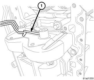
Place a dowel rod (1) through the holes in the balance shaft axles to keep the balance shafts in the correct position for reassembly.
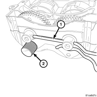
WARNING: The balance shaft pin must be installed before the balance shaft assembly is remove from the engine. The balance shaft pin must always remain in the balance shaft assembly while the assembly is removed from the engine. Do not remove the balance shaft pin until the balance shaft assembly is completely installed on the engine.
NOTE: The crankshaft must be positioned at 90° after TDC in order to install the Balance Shaft Locking Pin VM.10012 (2).
-
Insert the Balance Shaft Locking Pin VM.10012 (2) into the balance shaft assembly to lock the split gears together.
-
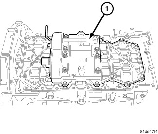
Remove bolts and the balance shaft housing (1).
INSTALLATION
INSTALLATION
Special Tools: Click to display a list of tools used in this procedure
|
-
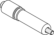
The balance shafts must remain aligned by the alignment dowel rod (1) and the Balance Shaft Locking Pin VM.10012 (2) must remain in the balance shaft assembly until the assembly is completely installed to the engine.
-
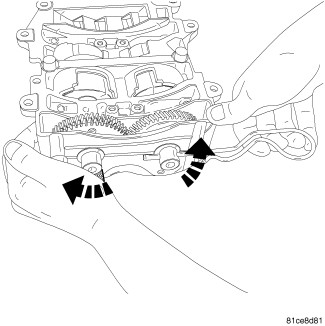
The balance shaft pin should never be removed from the balance shaft assembly when the balance shaft assembly is not installed in the engine. If the balance shaft was removed from the vehicle without the pin, or the pin was removed, use the dowel to load the spring while pressing the tool into place as shown.
-
Install the balance shaft housing (1) to the engine and tighten bolts finger tight.
-
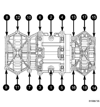
Using the sequence shown, tighten balance shaft bolts to 33 N·m (24 ft. lbs.).
- Remove Balance Shaft Locking Pin VM.10012 (2).
-
Remove the balance shaft assembly dowel rod (1).
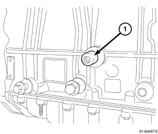
-
Remove the Crankshaft Locking Tool VM.9992 (1).
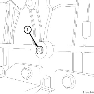
- Install the engine block plug (1). Tighten the engine block plug to 30 N·m (22 ft. lbs.).
- Install the upper and lower timing cover (Refer to 09 - Engine/Valve Timing/COVER(S) , Engine Timing - Installation).
- Install the oil pump pickup tube (Refer to 09 - Engine/Lubrication/PICK-UP, Oil Pump - Installation) .
- Fill the engine oil.
-
Connect the negative battery cable.