INSULATOR, Engine Mount, Left
REMOVAL
REMOVAL
Special Tools: Click to display a list of tools used in this procedure
 |
-
Disconnect the negative battery cable.
NOTE: The viscus fan does not need to be totally removed from vehicle only from the mounting drive.
- Remove the viscus fan and position aside (Refer to 07 - Cooling/Engine/DRIVE, Fan - Removal) .
- Raise and support the vehicle (Refer to 04 - Vehicle Quick Reference/Hoisting - Standard Procedure) .
- Remove the right side and left side lower engine mount nuts.
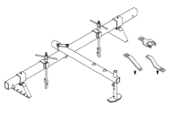
- Install the Fixture, Driveline Support 8534B .
- Raise the engine.
- Remove the left front tire.
- Remove the inner fender (Refer to 23 - Body/Exterior/SHIELD, Splash - Removal) .
-
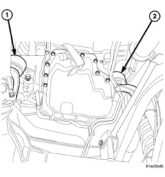
Remove upper nut, and the left engine mount (1).
INSTALLATION
INSTALLATION
Special Tools: Click to display a list of tools used in this procedure
|
- Position the left engine mount (1) and install the left upper retaining nut tight.
- Lower the vehicle.
- Lower the engine.
- Remove the Engine Support Fixture 8534B .
- Install the viscus fan (Refer to 07 - Cooling/Engine/DRIVE, Fan - Installation) .
- Tighten the left upper engine mount nut to 54 N·m (40 ft. lbs.).
- Raise and support the vehicle.
- Install the left and right lower engine mount nut. Tighten nut to 54 N·m (40 ft. lbs.).
- Lower the vehicle.
- Install the left inner splash shield (Refer to 23 - Body/Exterior/SHIELD, Splash - Installation) .
- Install the left front tire.
-
Connect the negative battery cable.