MODULE, Fuel Pump
DESCRIPTION
DESCRIPTION
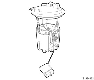 |
The fuel pump module is mounted on the top of the fuel tank and contains the following components:
- Mounting flange
- Electric fuel pump
- Fuel pump reservoir
- Inlet strainer
- Fuel pressure regulator
- Fuel level sending unit
- Fuel filter
The fuel level sending unit is the only serviceable component of the primary fuel pump module. If the electric fuel pump, fuel pressure regulator or fuel filter requires service, the primary fuel pump module must be replaced as an assembly.
OPERATION
OPERATION
An electric fuel pump is located within the fuel pump module. The electric fuel pump is a positive displacement, immersible pump with a permanent magnet electric motor capable of creating 860 kPa (125 psi) of operating pressure. The fuel pressure regulator limits fuel pressure to 400 kPa (58 psi).
The fuel gauge is controlled by the instrument cluster circuit board based upon cluster programming and a hard wired input received by the cluster from the fuel level sending unit on the module in the fuel tank.
The instrument cluster continually monitors the fuel tank sending unit to determine the level of fuel in the fuel tank. This information is available to other vehicle control modules via the Controller Area Network (CAN) data bus. Fuel gauge diagnosis is conducted as part of the instrument cluster circuitry (Refer to 08 - Electrical/8J - Instrument Cluster - Diagnosis and Testing)
.
REMOVAL
REMOVAL
Risk of injury to eyes and skin
from contact with fuel. Wear protective clothing and eye protection.
Risk of poisoning from inhaling and swallowing fuel. Pour fuel only
into appropriately marked and approved containers. Failure to follow
these instructions may result in possible serious or fatal injury.
WARNING:
The fuel system is under constant
high pressure even with engine OFF. Until the fuel pressure has been
properly released from the system, do not attempt to open the fuel
system. Do not smoke or use open flames/sparks when servicing the
fuel system. Make sure the area in which the vehicle is being serviced
is in a well ventilated area. Failure to comply may result in serious
or fatal injury.
WARNING:
 |
-
Drain and remove fuel tank (Refer to 14 - Fuel System/Fuel Delivery/TANK, Fuel - Removal)
.
NOTE: Prior to removing the fuel pump module, use compressed air to remove any accumulated dirt and debris from around fuel tank opening.
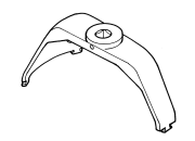
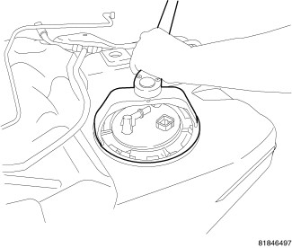
- Position the lock-ring remover/installer 9340 into the notches on the outside edge of the lock-ring.
- Install a 1/2 inch drive breaker bar into the lock-ring remover/installer 9340 .
-
Rotate the breaker bar counterclockwise and remove the lock-ring.
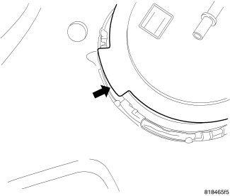
NOTE: The fuel pump module has to be properly located in the fuel tank for the fuel level gauge to work properly.
-
Mark the fuel pump module orientation.
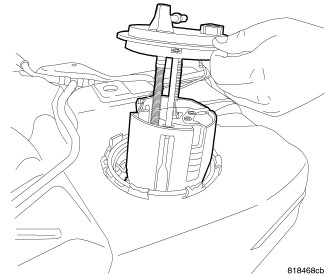
WARNING: The fuel pump module reservoir does not empty out when the tank is drained. The fuel in the reservoir will spill out when the module is removed.
NOTE: Do not spill fuel into the interior of the vehicle.
-
Raise the fuel pump module out of the fuel tank using caution not spill fuel inside the vehicle.
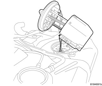
- Tip the fuel pump module on its side and drain all fuel from the reservoir.
-
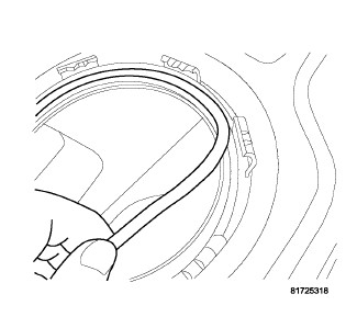
Remove the fuel pump module from the fuel tank using caution not to bend the float arm.
-
Remove and discard the rubber O-ring seal.
INSTALLATION
INSTALLATION
 |
Risk of injury to eyes and skin
from contact with fuel. Wear protective clothing and eye protection.
Risk of poisoning from inhaling and swallowing fuel. Pour fuel only
into appropriately marked and approved containers. Failure to follow
these instructions may result in possible serious or fatal injury.
WARNING:
Whenever the fuel pump module
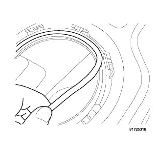
is serviced, the rubber O-ring seal must be replaced.
CAUTION:
-
Clean the rubber O-ring seal area of the fuel tank and install a new rubber O-ring seal.
-
Lower the fuel pump module into the fuel tank using caution not to bend the float arm.
NOTE: The main fuel pump module must be properly located in the fuel tank for the fuel level gauge to work properly.
-
Align the rubber O-ring seal and rotate the fuel pump module to the orientation marks noted during removal. This step must be performed for the fuel level gauge to work properly.
- Position the lock-ring over top of the fuel pump module.
- Position the lock-ring remover/installer 9340 into the notches on the outside edge of the lock-ring.
- Install a 1/2 inch drive breaker bar into the lock-ring remover/installer 9340 .
- Rotate the breaker bar clockwise until all seven notches of the lock-ring have engaged.
-
Install the fuel tank (Refer to 14 - Fuel System/Fuel Delivery/TANK, Fuel - Installation)
.