TANK, Fuel
REMOVAL
REMOVAL
Risk of injury to eyes and skin
from contact with fuel. Wear protective clothing and eye protection.
Risk of poisoning from inhaling and swallowing fuel. Pour fuel only
into appropriately marked and approved containers. Failure to follow
these instructions may result in possible serious or fatal injury.
WARNING:
The fuel system is under constant
high pressure even with engine OFF. Until the fuel pressure has been
properly released from the system, do not attempt to open the fuel
system. Do not smoke or use open flames/sparks when servicing the
fuel system. Make sure the area in which the vehicle is being serviced
is in a well ventilated area. Failure to comply may result in serious
or fatal injury.
WARNING:
 |
- Perform Fuel System Pressure Release Procedure (Refer to 14 - Fuel System/Fuel Delivery - Standard Procedure) .
- If possible, drain the fuel tank using the Conventional Procedure (Refer to 14 - Fuel System/Fuel Delivery - Standard Procedure) .
- Disconnect and isolate the negative battery cable.
- Remove the fuel filler cap to relieve tank pressure.
- Raise and support the vehicle (Refer to 04 - Vehicle Quick Reference/Hoisting - Standard Procedure) .
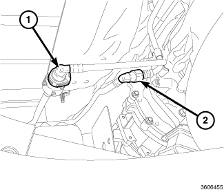
- Disconnect the EVAP solenoid to vapor canister line quick-connect fitting (2) (Refer to 14 - Fuel System/Fuel Delivery/FITTING, Quick Connect - Standard Procedure) .
-
Disconnect the fuel pump module to fuel rail line quick-connect fitting (1) (Refer to 14 - Fuel System/Fuel Delivery/FITTING, Quick Connect - Standard Procedure)
.
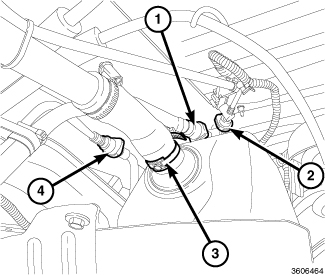
- Loosen the fuel filler tube hose clamp (3) and remove the fuel filler tube from the fuel tank.
- Disconnect the EVAP solenoid to vapor canister line quick-connect fitting (4) (Refer to 14 - Fuel System/Fuel Delivery/FITTING, Quick Connect - Standard Procedure) .
- Disconnect the On-Board Refueling Vapor Recovery (ORVR) vacuum line quick-connect fitting (2) from the ORVR control valve (Refer to 14 - Fuel System/Fuel Delivery/FITTING, Quick Connect - Standard Procedure) .
-
Disconnect the vapor canister line quick-connect fitting (1) from the ORVR control valve (Refer to 14 - Fuel System/Fuel Delivery/FITTING, Quick Connect - Standard Procedure)
.
-
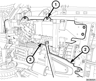
Remove the transfer case skid plate (2) (Refer to 13 - Frame and Bumpers/Under Body Protection/PLATE, Skid - Removal)
.
NOTE: The fuel tank skid plate and the fuel tank assembly are removed at the same time. They share common fasteners.
- Position a support fixture under the fuel tank (3) such as OTC® Fuel Tank Handler 1758 on the OTC® High-Lift Transmission Jack 1728.
-
Remove eight bolts (1) and partially lower the fuel tank to gain access to the fuel pump module electrical connector.
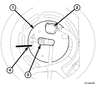
- Disconnect the electrical connector (2) from the fuel pump module (1).
- Continue lowering the fuel tank for removal.
- If required, lift the fuel tank from the skid plate.
-
If required, remove the fuel pump module from the fuel tank (Refer to 14 - Fuel System/Fuel Delivery/MODULE, Fuel Pump - Removal)
.
INSTALLATION
INSTALLATION
|
- If removed, install the fuel pump module to the fuel tank (Refer to 14 - Fuel System/Fuel Delivery/MODULE, Fuel Pump - Installation) .
-
If removed, install the fuel tank in the skid plate.
NOTE: The fuel tank skid plate and the fuel tank assembly are installed at the same time. They share common fasteners.
- Position a support fixture under the fuel tank (3) such as OTC® Fuel Tank Handler 1758 on the OTC® High-Lift Transmission Jack 1728.
-
Partially raise the fuel tank and connect the electrical connector (2) to the fuel pump module (1).
- Continue raising the fuel tank (3) to the body.
- Install eight bolts (1) and tighten to 65 N·m (48 ft. lbs.).
-
Install the transfer case skid plate (2) (Refer to 13 - Frame and Bumpers/Under Body Protection/PLATE, Skid - Installation)
.
- Connect the EVAP solenoid to vapor canister line quick-connect fitting (2) (Refer to 14 - Fuel System/Fuel Delivery/FITTING, Quick Connect - Standard Procedure) .
-
Connect the fuel pump module to fuel rail line quick-connect fitting (1) (Refer to 14 - Fuel System/Fuel Delivery/FITTING, Quick Connect - Standard Procedure)
.
- Connect the vapor canister line quick-connect fitting (1) to the On-Board Refueling Vapor Recovery (ORVR) control valve (Refer to 14 - Fuel System/Fuel Delivery/FITTING, Quick Connect - Standard Procedure) .
- Connect the ORVR vacuum line quick-connect fitting (2) to the ORVR control valve (Refer to 14 - Fuel System/Fuel Delivery/FITTING, Quick Connect - Standard Procedure) .
- Connect the EVAP solenoid to vapor canister line quick-connect fitting (4) (Refer to 14 - Fuel System/Fuel Delivery/FITTING, Quick Connect - Standard Procedure) .
- Install the fuel filler tube to the fuel tank and tighten the hose clamp (3) to 3 N·m (30 in. lbs.).
- Lower the vehicle.
- If required, fill the fuel tank (Refer to 04 - Vehicle Quick Reference/Capacities and Recommended Fluids - Specifications) .
- Install the fuel filler cap.
- Connect the negative battery cable and tighten nut to 5 N·m (45 in. lbs.).
-
Start the vehicle and check for leaks.