INJECTOR(S), Fuel
DESCRIPTION
DESCRIPTION
To control the injection valves, the new Common-Rail injectors use a rapid-action actuator made of piezo crystals, which opens and closes the injection valve. The piezo crystals expand when electrical current is applied to them, and contract when electrical current is turned off. The piezo actuator can switch up to five times faster than a standard solenoid, because the movement of the piezo crystals does not rely on mechanical components to transmit motion to the injection valve. This doubles the piezo injector's switching speed, and enables fuel to be delivered with greater precision, which leads to lower emissions and better engine performance.
STANDARD PROCEDURE - INJECTOR CLASSIFICATION
STANDARD PROCEDURE - INJECTOR CLASSIFICATION
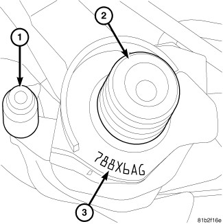 |
Each fuel injector has a alphanumeric correction code number. This correction code is printed on the upper part of the fuel injector (3) and is used to identify injector calibration. When replacing any fuel injectors, this code must be entered into the vehicles Powertrain Control Module (PCM) using a diagnostic scan tool. In addition, if a new PCM is installed, use a diagnostic scan tool to program all of the injector codes from the original fuel injectors into the new PCM.
The classification of injectors describes the fuel flow quantity characteristic of the injector. This will make it possible in the future to match the engine software to the tolerances of the injector within a more narrowly graduated range. Classification can be clearly recognized, and assigned only by means of a scan tool.
These general conditions equally apply if, as a result of replacing an engine, carrying out repairs to the cylinder head etc., the cylinder selective assignment of the injectors or the engine control module assignment may have changed. If proper attention is not paid to the classification on these vehicles, driveability and smoking concerns could result.
If an injector is replaced, it is then necessary to assign the classification code to the corresponding cylinder in the PCM with the appropriate scan tool.
INJECTOR CLASSIFICATION PROCEDURE
- Turn ignition switch “ON”.
- Using the diagnostic scan tool, select ENGINE then MISCELLANEOUS.
- Select LEARN INJECTORS.
- Using the up and down arrows, scroll to the appropriate injector.
- Using the right and left arrows, set injector to proper classification code.
- Once injectors are classified, cycle ignition key to complete.
REMOVAL
REMOVAL

Due to the complexity of the fuel
injection system used on this engine, refer to the Diesel Engine Diagnostics,
and service any fuel system DTCs prior to replacing any fuel injectors.
If no DTCs are present, refer to the Diesel Engine Diagnostic Test
for Lack of Engine Power, and perform all steps as directed prior
to replacing any fuel injectors.
CAUTION:
Cleanliness cannot be overemphasized
when handling or replacing diesel fuel system components. This especially
includes the fuel injectors, high-pressure fuel lines and fuel injection
pump. Very tight tolerances are used with these parts. Dirt contamination
could cause rapid part wear and possible plugging of fuel injector
nozzle tip holes. This in turn could lead to possible engine misfire.
Always wash/clean any fuel system component thoroughly before disassembly
and then air dry. Cap or cover any open part after disassembly. Before
assembly, examine each part for dirt, grease or other contaminants
and clean if necessary. When installing new parts, lubricate them
with clean engine oil or clean diesel fuel only. DO NOT use any lubricating
or sliding agents that contain water.
CAUTION:
- Disconnect the negative battery cable.
-
Remove the four nuts and the engine cover.
NOTE: Label the location of each high pressure fuel line with the cylinder in which it was removed.
-
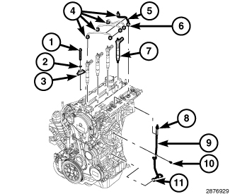
Remove the high-pressure fuel tubes (5) from fuel rail (6) and fuel injectors (4) and install a protective cap on the fuel injector (7) and fuel rail.
-
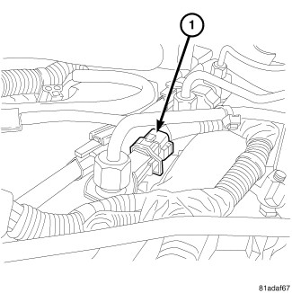
Disconnect the fuel injector(s) harness connector.
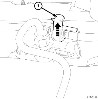
NOTE: The injector common fuel return line is connected to the low pressure fuel circuit (5 bar/72 psi).
-
A lock button (1) is used to secure the common fuel return line to each fuel injector. Use your fingers to lift up all four lock buttons (1) to unlock. After unlocking all four buttons, lift up fuel return line assembly to remove.
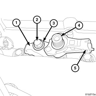
- Remove injector mounting bolt (2) and washer (3) and mounting clamp (1).
-
Using compressed air, thoroughly clean surface area in and around injector bore to prevent foreign material from falling into the injector bore after injector removal.
NOTE: Label the location of each fuel injector to the cylinder in which it was removed .
-
Using your hand, pull fuel injector (4) straight up from cylinder head for removal. After removing the injector, place a protective cap over the nozzle.
-
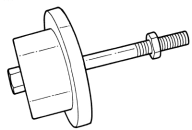
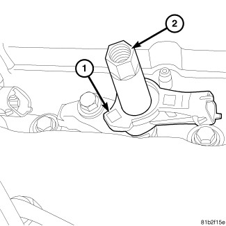
If injector can't be removed by hand, install Fuel Injector Removal Tool 9552 (2) to top of fuel injector (1).
-
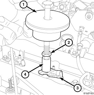
Install Slide Hammer Tool 8941 (1) onto Fuel Injector Remover Tool 9552 (4). Tighten lock nut (2). Remove injector from cylinder head.
INSTALLATION
INSTALLATION
Due to the complexity of the fuel
injection system used on this engine, refer to the Diesel Engine Diagnostics,
and service any fuel system DTCs prior to replacing any fuel injectors.
If no DTCs are present, refer to the Diesel Engine Diagnostic Test
for Lack of Engine Power, and perform all steps as directed prior
to replacing any fuel injectors.
CAUTION:
Cleanliness cannot be overemphasized
when handling or replacing diesel fuel system components. This especially
includes the fuel injectors, high-pressure fuel lines and fuel injection
pump. Very tight tolerances are used with these parts. Dirt contamination
could cause rapid part wear and possible plugging of fuel injector
nozzle tip holes. This in turn could lead to possible engine misfire.
Always wash/clean any fuel system component thoroughly before disassembly
and then air dry. Cap or cover any open part after disassembly. Before
assembly, examine each part for dirt, grease or other contaminants
and clean if necessary. When installing new parts, lubricate them
with clean engine oil or clean diesel fuel only. DO NOT use any lubricating
or sliding agents that contain water.
CAUTION:
 |
| NOTE: |
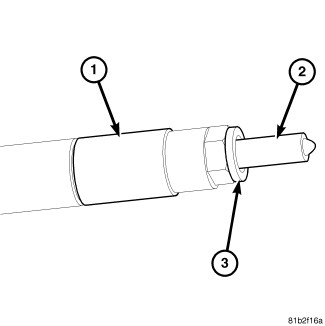
DO NOT use a brush to clean around the injector nozzle (2). DO NOT lubricate area around injector nozzle. The injector may become restricted with debris. |
| NOTE: |
Be sure a new copper washer/seal (3) is installed on end of injector and the old seal is removed, before installing in cylinder head. |
| NOTE: |
No force should be used in installing the fuel injector. Do not apply any pressure to the electrical connector or the fuel return port during the installation process. |
-
Install a new O-ring on the fuel injector return nipple.
NOTE: Use care not to get any grease on injector nozzle.
- Lubricate the injector body with Lubriplate all purpose white grease.
-
Using a new copper sealing washer (3), install fuel injector into cylinder head.
- Install fuel injector retainer clamp (1), washer (3) and a new bolt (2). Tighten bolt (2) to 33 N·m (24 ft. lbs.).
-
Remove the protective caps and install fuel injector high-pressure tubes (Refer to 14 - Fuel System/Fuel Delivery/TUBE(S)
, Fuel - Installation).
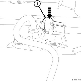
NOTE: Be sure lock buttons (1) are in up position before positioning.
-
Position female fittings on fuel return line to male fittings at each fuel injector.
-
After positioning, push down on each lock button (1) to secure fuel return line to each fuel injector.
- Connect each fuel injector harness connector.
- Connect the negative battery cable.
- Perform the injector classification procedure with a diagnostic scan tool.
- Start the engine and inspect for fuel leaks.
-
Install the engine cover and securely tighten the four nuts.