SENSOR, Oxygen
DESCRIPTION
DESCRIPTION
The Oxygen Sensors (O2S) are attached to, and protrude into the vehicle exhaust system. Four sensors are used: 2 upstream (referred to as 1/1 and 2/1) and 2 downstream (referred to as 1/2 and 2/2).
The upstream sensors (1/1 and 2/1) are located in the exhaust of the cylinder bank just before the catalytic convertor. The downstream sensors (1/2 and 2/2) are located in the exhaust downpipe of the cylinder bank just after the catalytic convertor.
REMOVAL
REMOVAL
Never apply any type of grease
to the oxygen sensor electrical connector, or attempt any repair of
the sensor wiring harness.
CAUTION:
The exhaust manifold, exhaust
pipes and catalytic converter become very hot during engine operation.
Allow engine to cool before removing oxygen sensor.
WARNING:
The engine is equipped with four heated oxygen sensors:
- The right upstream oxygen sensor is referred to as the 1/1 sensor.
- The right downstream oxygen sensor is referred to as the 1/2 sensor.
- The left upstream oxygen sensor is referred to as the 2/1 sensor.
-
The left downstream oxygen sensor is referred to as the 2/2 sensor.
Right Oxygen Sensor(s)
 |
- Disconnect and isolate the negative battery cable.
- Raise and support the vehicle (Refer to 04 - Vehicle Quick Reference/Hoisting - Standard Procedure) .
-
Remove the right front wheelhouse inner splash shield (Refer to 23 - Body/Exterior/SHIELD, Splash - Removal)
.
CAUTION: When disconnecting the oxygen sensor electrical connector, do not pull directly on the wire going into the sensor. The sensor wiring can be damaged resulting in sensor failure.
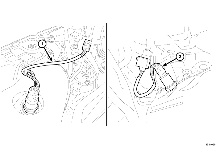
- Disconnect the electrical connector from the right upstream 1/1 oxygen sensor (1) or the right downstream 1/2 oxygen sensor (2).
- Remove the oxygen sensor.
-
Clean the threads in the exhaust pipe using an appropriate tap.
Left Oxygen Sensor(s)
 |
- Disconnect and isolate the negative battery cable.
- Raise and support the vehicle (Refer to 04 - Vehicle Quick Reference/Hoisting - Standard Procedure) .
-
Remove the left front wheelhouse inner splash shield (Refer to 23 - Body/Exterior/SHIELD, Splash - Removal)
.
CAUTION: When disconnecting the oxygen sensor electrical connector, do not pull directly on the wire going into the sensor. The sensor wiring can be damaged resulting in sensor failure.
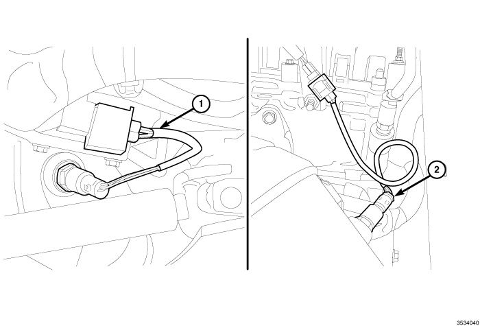
- Disconnect the electrical connector from the left upstream 2/1 oxygen sensor (1) or the left downstream 2/2 oxygen sensor (2).
- Remove the oxygen sensor.
-
Clean the threads in the exhaust pipe using an appropriate tap.
INSTALLATION
INSTALLATION
Never apply any type of grease
to the oxygen sensor electrical connector, or attempt any repair of
the sensor wiring harness.
CAUTION:
The engine is equipped with four heated oxygen sensors:
- The right upstream oxygen sensor is referred to as the 1/1 sensor.
- The right downstream oxygen sensor is referred to as the 1/2 sensor.
- The left upstream oxygen sensor is referred to as the 2/1 sensor.
-
The left downstream oxygen sensor is referred to as the 2/2 sensor.
Right Oxygen Sensor(s)
|
- If reinstalling the original oxygen sensor, coat the sensor threads with an anti-seize compound such as Loctite 771-64 or equivalent. New sensors have compound on the threads and do not require additional coating. Do Not add any additional anti-seize compound to the threads of a new oxygen sensor.
- Install the right upstream 1/1 oxygen sensor (1) or the right downstream 1/2 oxygen sensor (2) and tighten to 50 N·m (37 ft. lbs.).
- Connect the oxygen sensor electrical connector.
- Install the right front wheelhouse inner splash shield (Refer to 23 - Body/Exterior/SHIELD, Splash - Installation) .
- Lower the vehicle.
-
Connect the negative battery cable and tighten nut to 5 N·m (45 in. lbs.).
Left Oxygen Sensor(s)
|
- If reinstalling the original oxygen sensor, coat the sensor threads with an anti-seize compound such as Loctite 771-64 or equivalent. New sensors have compound on the threads and do not require additional coating. Do Not add any additional anti-seize compound to the threads of a new oxygen sensor.
- Install the left upstream 2/1 oxygen sensor (1) or the left downstream 2/2 oxygen sensor (2) and tighten to 50 N·m (37 ft. lbs.).
- Connect the oxygen sensor electrical connector.
- Install the left front wheelhouse inner splash shield (Refer to 23 - Body/Exterior/SHIELD, Splash - Installation) .
- Lower the vehicle.
-
Connect the negative battery cable and tighten nut to 5 N·m (45 in. lbs.).