ROTOR, Brake
- DISC BRAKE ROTOR
- BRAKE DRUM IN HAT ROTOR
- DISC BRAKE ROTORS
- BRAKE DRUM IN HAT ROTOR MACHINING
- FRONT
- REAR
- FRONT
- REAR
DISC BRAKE ROTOR
DISC BRAKE ROTOR
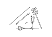
The rotor braking surfaces should not be refinished unless necessary.
Light surface rust and scale can be removed with a lathe equipped with dual sanding discs. The rotor surfaces can be restored by machining in a disc brake lathe if surface scoring and wear are light.
Replace the rotor under the following conditions:
ROTOR MINIMUM THICKNESS
Measure rotor thickness at the center of the brake shoe contact surface. Replace the rotor if worn below minimum thickness, or if machining would reduce thickness below the allowable minimum.
Rotor minimum thickness is usually specified on the rotor hub. The specification is either stamped or cast into the hub surface.
ROTOR RUNOUT
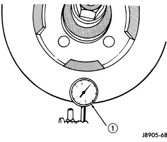 |
Check rotor lateral runout with dial indicator C-3339A . Excessive lateral runout will cause brake pedal pulsation and rapid, uneven wear of the brake shoes. Position the dial indicator (1) plunger approximately 6.35 mm (1/4 in.) inward from the rotor edge.
| NOTE: |
Be sure wheel bearing has zero end play before checking rotor runout. |
Maximum allowable rotor runout is 0.102 mm (0.004 in.).
ROTOR THICKNESS VARIATION
 |
Variations in rotor thickness will cause pedal pulsation, noise and shudder.
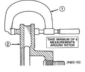
Measure rotor thickness at 6-to-12 points around the rotor face .
Position the micrometer (1) approximately 25.4 mm ( 1 in.) from the rotor outer circumference for each measurement.
Thickness should not vary by more than 0.013 mm (0.0005 in.) from point-to-point on the rotor. Machine or replace the rotor if necessary.
BRAKE DRUM IN HAT ROTOR
BRAKE DRUM IN HAT ROTOR
The maximum allowable diameter of the drum braking surface is indicated on the drum outer edge. Always replace the drum if machining would cause drum diameter to exceed the size limit indicated on the drum in hat.
BRAKE DRUM RUNOUT
Measure drum diameter and runout with an accurate gauge. The most accurate method of measurement involves mounting the drum in a brake lathe and checking variation and runout with a dial indicator.
Machine the drum if runout or variation exceed values. Replace the drum in hat rotor if machining causes the drum in hat rotor to exceed the maximum allowable diameter.
DISC BRAKE ROTORS
DISC BRAKE ROTORS
| NOTE: |
A hub mounted on-vehicle lathe is highly recommended. This type of lathe trues the rotor to the vehicles hub/bearing. |
The disc brake rotor can be machined if scored or worn. The on-vehicle lathe must machine both sides of the rotor simultaneously with dual cutter heads. The rotor mounting surface must be clean before placing on the on-vehicle lathe. Equipment capable of machining only one side at a time may produce a tapered rotor This type of rotor machining is not recommended.
| NOTE: |
Proper wheel torque is also critical to help prevent any warping of the disc brake rotor. |
Brake rotors that do not meet
minimum thickness specifications before or after machining must be
replaced.
CAUTION:
BRAKE DRUM IN HAT ROTOR MACHINING
BRAKE DRUM IN HAT ROTOR MACHINING
The brake drum in hat rotor can be machined on a drum lathe when necessary. Initial machining cuts should be limited to 0.12 - 0.20 mm (0.005 - 0.008 in.) at a time as heavier feed rates can produce taper and surface variation. Final finish cuts of 0.025 to 0.038 mm (0.001 to 0.0015 in.) are recommended and will generally provide the best surface finish.
Be sure the drum in hat rotor is securely mounted in the lathe before machining operations. A damper strap should always be used around the drum to reduce vibration and avoid chatter marks.
The maximum allowable diameter of the drum braking surface is stamped or cast into the drum in hat rotor.
Replace the drum in hat rotor
if machining will cause the drum to exceed the maximum allowable diameter.
CAUTION:
FRONT
FRONT
 |
- Remove wheel and tire assemble.
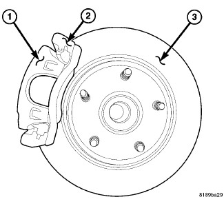
- Remove caliper (1). (Refer to 05 - Brakes/Hydraulic/Mechanical/CALIPER, Disc Brake - Removal) .
- Remove retainers securing rotor to hub studs .
- Remove rotor (3) from hub.
- If rotor shield requires service, remove front hub and bearing assembly.
REAR
REAR
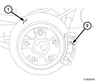 |
- Raise and support the vehicle
-
Remove the tire and wheel assembly.
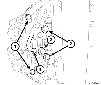
CAUTION: Never allow the disc brake caliper to hang from the brake hose. Damage to the brake hose will result. Provide a suitable support to hang the caliper securely.
- Remove the disc brake caliper adapter (2) (Refer to 05 - Brakes/Hydraulic/Mechanical/ADAPTER, Disc Brake Caliper - Removal) .
-
Remove the retaining clips and rotor assembly.
FRONT
FRONT
|
- Clean the hub from any rust before installing the rotor.
- Install rotor on hub.
- Install caliper. (Refer to 05 - Brakes/Hydraulic/Mechanical/CALIPER, Disc Brake - Installation) .
- Install wheel and tire assembly. (Refer to 22 - Tires and Wheels/Wheels - Standard Procedure) .
REAR
REAR
|
- Install the rotor to the axle shaft.
-
Install the disc brake caliper adapter (2) (Refer to 05 - Brakes/Hydraulic/Mechanical/ADAPTER, Disc Brake Caliper - Installation)
.
- Install the tire and wheel assembly (Refer to 22 - Tires and Wheels/Wheels - Standard Procedure) .
-
Lower the vehicle.