TUBES AND HOSES, Brake
- DESCRIPTION
- OPERATION
- DIAGNOSIS AND TESTING - BRAKE LINE AND HOSES
- DOUBLE INVERTED FLARING
- ISO FLARING
- FRONT BRAKE HOSE
- REAR BRAKE HOSE
- FRONT BRAKE HOSE
- REAR BRAKE HOSE
DESCRIPTION
DESCRIPTION
Flexible rubber hose is used at both front brakes and at the rear axle junction block. Double walled steel tubing is used to connect the master cylinder to the major hydraulic braking components and then to the flexible rubber hoses. Double inverted style and ISO style flares are used on the brake lines.
OPERATION
OPERATION
The hoses and lines transmit the brake fluid hydraulic pressure to the calipers and or wheel cylinders.
DIAGNOSIS AND TESTING - BRAKE LINE AND HOSES
DIAGNOSIS AND TESTING - BRAKE LINE AND HOSES
Flexible rubber hose is used at both front brakes and at the rear axle junction block. Inspect the hoses whenever the brake system is serviced, at every engine oil change, or whenever the vehicle is in for service.
Inspect the hoses for surface cracking, scuffing, or worn spots. Replace any brake hose immediately if the fabric casing of the hose is exposed due to cracks or abrasions.
Also check brake hose installation. Faulty installation can result in kinked, twisted hoses, or contact with the wheels and tires or other chassis components. All of these conditions can lead to scuffing, cracking and eventual failure.
The steel brake lines should be inspected periodically for evidence of corrosion, twists, kinks, leaks, or other damage. Heavily corroded lines will eventually rust through causing leaks. In any case, corroded or damaged brake lines should be replaced.
Factory replacement brake lines and hoses are recommended to ensure quality, correct length and superior fatigue life. Care should be taken to make sure that brake line and hose mating surfaces are clean and free from nicks and burrs. Also remember that right and left brake hoses are not interchangeable.
Use new copper seal washers at all caliper connections. Be sure brake line connections are properly made (not cross threaded) and tightened to recommended torque.
DOUBLE INVERTED FLARING
DOUBLE INVERTED FLARING
A preformed metal brake tube is recommended and preferred for all repairs. However, double-wall steel tube can be used for emergency repair when factory replacement parts are not readily available.
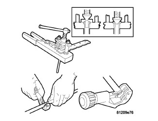 |
- Cut off damaged tube with Tubing Cutter.
- Ream cut edges of tubing to ensure proper flare.
- Install replacement tube nut on the tube.
- Insert tube in flaring tool.
- Place gauge form over the end of the tube.
- Push tubing through flaring tool jaws until tube contacts recessed notch in gauge that matches tube diameter.
- Tighten the tool bar on the tube
- Insert plug on gauge in the tube. Then swing compression disc over gauge and center tapered flaring screw in recess of compression disc.
- Tighten tool handle until plug gauge is squarely seated on jaws of flaring tool. This will start the inverted flare.
-
Remove the plug gauge and complete the inverted flare.
ISO FLARING
ISO FLARING
A preformed metal brake tube is recommended and preferred for all repairs. However, double-wall steel tube can be used for emergency repair when factory replacement parts are not readily available.
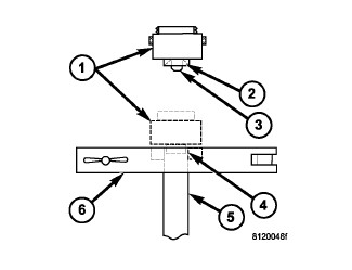 |
To make a ISO flare use an ISO flaring tool kit.
- Cut off damaged tube with Tubing Cutter.
- Remove any burrs from the inside of the tube.
- Install tube nut on the tube.
- Position the tube in the flaring tool flush with the top of the tool bar (6). Then tighten the tool bar on the tube.
- Install the correct size adaptor (1) on the flaring tool yoke screw.
- Lubricate the adaptor (2).
- Align the adaptor and yoke screw over the tube.
-
Turn the yoke screw in until the adaptor is squarely seated on the tool bar.
FRONT BRAKE HOSE
FRONT BRAKE HOSE
 |
- Install a prop rod on the brake pedal to keep pressure on the brake system. Holding the pedal in this position will isolate the master cylinder from the hydraulic brake system and will not allow brake fluid to drain out of the brake fluid reservoir while brake lines are open. This will allow you to bleed out the area of repair instead of the entire system.
- Raise and support vehicle (Refer to 04 - Vehicle Quick Reference/Hoisting - Standard Procedure) .
- Remove the tire and wheel assembly.
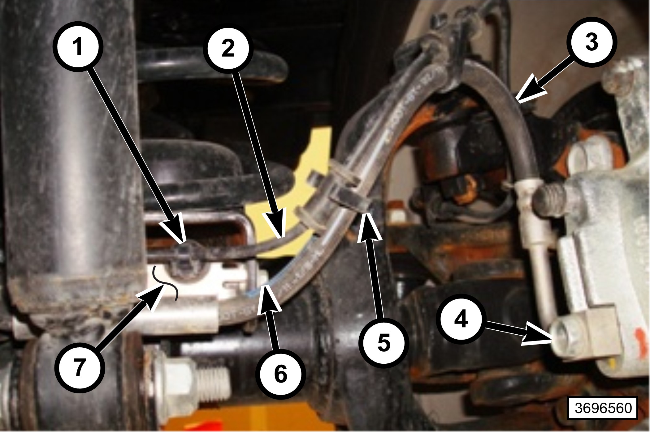
- Remove the wheel speed sensor wire (2) from all brake hose clips (5).
- Remove the two wheel speed sensor push in type retainers (1) from the brake hose spring bracket (7).
- Remove the brake hose spring bracket bolt (6).
-
Remove the brake hose banjo bolt (4) at the caliper.
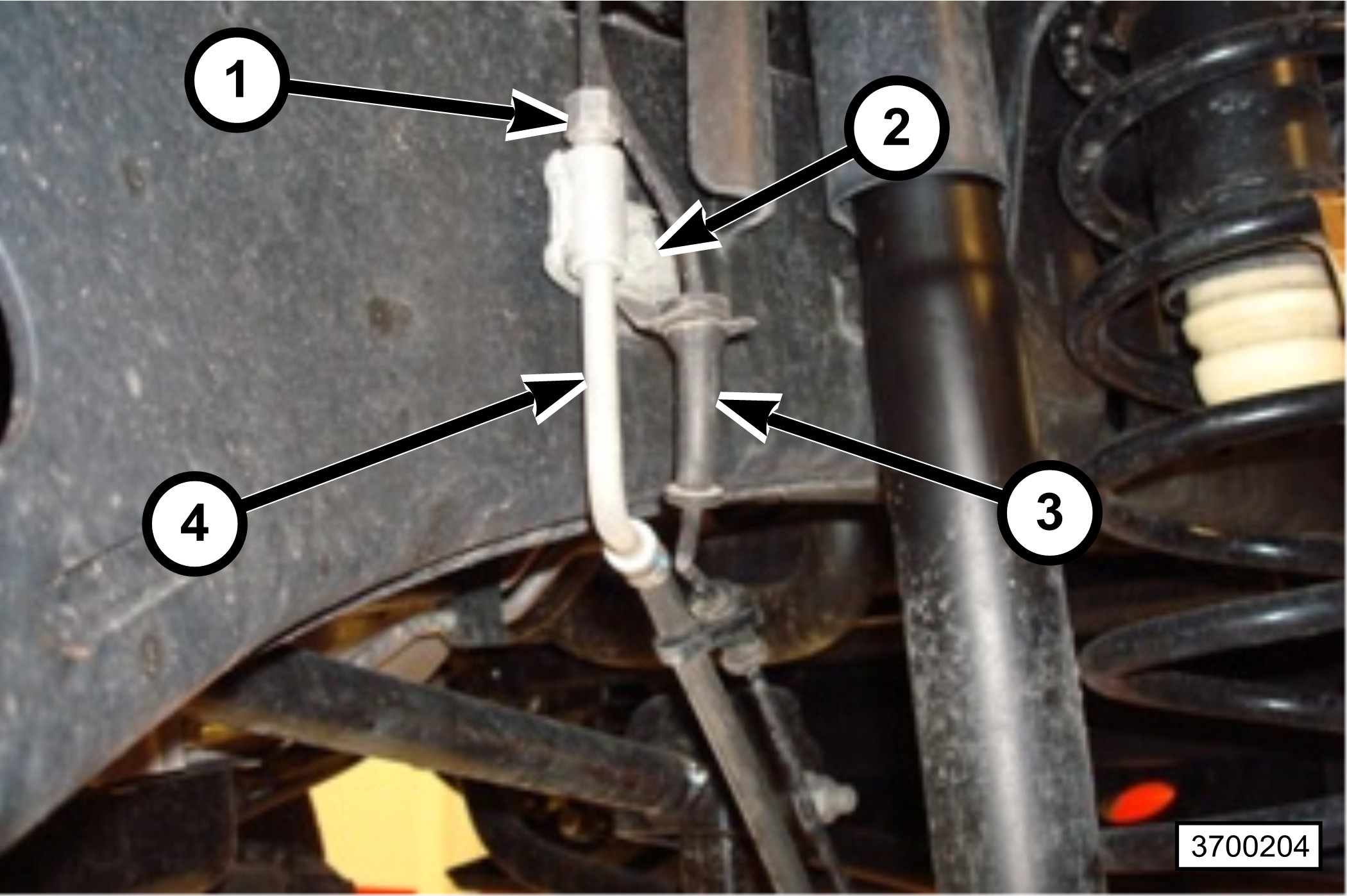
- Remove the wheel speed sensor wire (3) from the brake hose to frame routing clip on the brake hose (4).
- Remove the brake line tube nut (1) from the brake hose (4) at the frame.
-
Remove the mounting bolt (3) at the brake hose to frame routing clip to remove the brake hose (4).
REAR BRAKE HOSE
REAR BRAKE HOSE
 |
- Install prop rod on the brake pedal to keep pressure on the brake system, Holding pedal in this position will isolate master cylinder from hydraulic brake system and will not allow brake fluid to drain out of brake fluid reservoir while brake lines are open. This will allow you to bleed out the area of repair instead of the entire system.
- Raise and support vehicle.
-
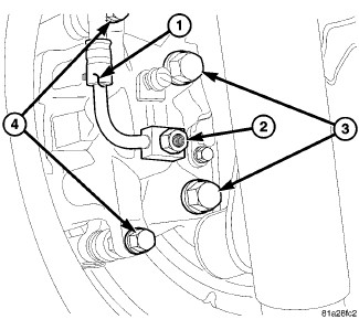
Remove the banjo bolt (2) from the rear caliper for the brake hose (1).
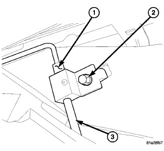
- Remove the rear brake line (1) from the brake hose (3) at the frame.
- Remove the mounting bolt (2) for the brake hose (3) at the frame.
-
Remove the brake hose (3).
FRONT BRAKE HOSE
FRONT BRAKE HOSE
|
- Position the brake hose (4).
- Install the mounting bolt (2) for the brake hose to the frame routing clip and tighten to 20 N·m (177 in. lbs.).
- Install the brake line tube nut (1) to the brake hose (4) and tighten to 12 N·m (105 in. lbs.).
-
Attach the wheel speed sensor wire (3) to the routing clip on the brake hose to frame routing clip.
- Position the brake hose spring bracket (7), install the bolt (6) and tighten to 8 N·m (71 in. lbs.).
-
Using two new copper washers, install the brake hose banjo bolt (4) at the caliper and tighten to 32 N·m (24 ft. lbs.).
NOTE: All clips must be attached for proper routing.
- Attach the wheel speed sensor wire (2) to all brake hose clips (5).
- Attach the two wheel speed sensor push in type retainers (1) to the brake hose bracket (7).
- Remove the supports and lower the vehicle.
- Remove the prop rod from the vehicle.
-
Bleed the area of repair for the brake system, If a proper pedal is not felt during bleeding an area of repair then a base bleed system must be performed
(Refer to 05 - Brakes - Standard Procedure)
.
REAR BRAKE HOSE
REAR BRAKE HOSE
|
- Install the brake hose (3) to the mounting hole at the frame and install the mounting bolt (2).
-
Install the brake line tube nut (1) to the brake hose (3) and tighten to 23 N·m (200 in. lbs.) torque.
- Install banjo bolt (2) attaching brake hose (1) to caliper. Install NEW washers on each side of hose fitting as banjo bolt is placed through banjo fitting. Thread banjo bolt into caliper and tighten to 31 N·m (23 ft. lbs.) torque.
- Lower vehicle.
- Remove the prop rod from the vehicle.
-
Bleed the area of repair for the brake system, If a proper pedal is not felt during bleeding an area of repair then a base bleed system must be performed.
(Refer to 05 - Brakes - Standard Procedure)
.