SWITCH, Multifunction, Left
DESCRIPTION
DESCRIPTION
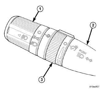 |
The left (lighting) multi-function switch is located on the left side of the steering column, just below the steering wheel. This switch is the primary control for the interior and exterior lighting systems. The only visible components of the switch are the control stalk (2), control knob (1) and control sleeve (3) that extend through the steering column shrouds on the left side of the column. The remainder of the switch including its mounting provisions, its electrical connection, and the turn signal cancel actuator are concealed beneath the shrouds.
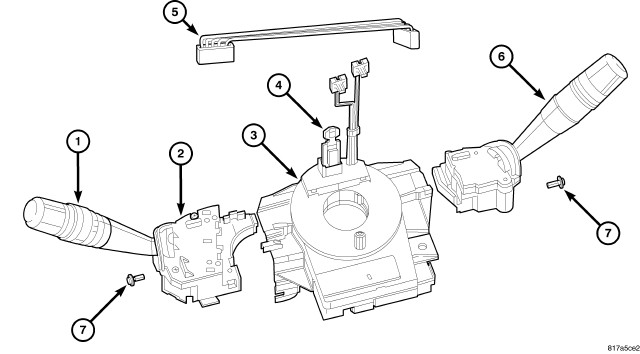 |
The switch housing (2) and controls (1) are constructed of molded black plastic. Each of the switch controls has white International Control and Display Symbol graphics applied to it, which clearly identify its many functions. A single screw (7) through a mounting tab integral to the back of the switch housing, and a slide tab integral to the bottom of the switch housing secure the switch to the mounting bracket integral to the clockspring (3).
The Steering Control Module (SCM) is internal to the switch housing. The switch outputs are internally connected directly to the SCM. A single connector receptacle containing seven terminal pins is integral to the inboard end of the switch housing and connects the right multi-function switch (6) through a jumper wire harness (5) directly to the SCM. An integral connector receptacle on the back of the switch housing connects the SCM to the vehicle electrical system through a dedicated take out and connector of the instrument panel wire harness.
The left multi-function switch provides the vehicle operator with a control interface for the following exterior lighting system functions:
- Front Fog Lamps - For vehicles so equipped, the left multi-function switch control knob provides detent switching for the optional front fog lamps.
- Headlamps - The left multi-function switch control knob provides detent switching for the headlamps.
- Headlamp Beam Selection - The left multi-function switch control stalk provides detent switching for selection of the headlamp high or low beams.
- Headlamp Optical Horn - The left multi-function switch control stalk includes momentary switching of the headlamp high beam circuits to provide an optical horn feature (sometimes referred to as flash-to-pass), which allows the vehicle operator to momentarily flash the headlamp high beams as an optical signalling device.
- Park Lamps - The left multi-function switch control knob provides detent switching for the park lamps.
- Rear Fog Lamps - For vehicles so equipped, the left multi-function switch control knob provides detent switching for the optional rear fog lamps. Rear fog lamps are optional only for vehicles manufactured for certain markets, where they are required.
- Turn Signal Control - The left multi-function switch control stalk provides both momentary non-detent switching and detent switching with automatic cancellation for both the left and right turn signal lamps.
The left multi-function switch also provides the vehicle operator with a control interface for the following interior lighting functions:
- Interior Lamps Defeat - The left multi-function switch control ring provides detent switching to DEFEAT the illumination of all interior courtesy lamps when a door, the rear flip-up glass, or the liftgate are opened.
- Interior Lamps On - The left multi-function switch control ring provides detent switching to simultaneously illuminate all interior courtesy lamps.
- Panel Lamps Dimming - The left multi-function switch control ring provides simultaneous adjustable control of the illumination intensity of all instrument panel lighting at one of five available illumination intensity levels.
- Parade Mode - The left multi-function switch control ring provides detent switching for a PARADE mode that maximizes the illumination intensity of all instrument panel lighting for visibility when driving in daylight with the exterior lamps turned ON.
The left multi-function switch cannot be adjusted or repaired. If any function of the switch is ineffective, or if the switch is damaged, the entire switch unit must be replaced. The clockspring (with the multi-function switch mounting bracket), the left multi-function switch (with the SCM), the right multi-function switch and the jumper wire harness are each available for separate service replacement.
OPERATION
OPERATION
The left (lighting) multi-function switch uses resistor multiplexing to control the many functions and features it provides using a minimal number of hard wired circuits. The switch receives clean grounds from the Steering Control Module (SCM), then provides resistor multiplexed return outputs to the SCM to indicate the selected switch positions. The SCM then sends electronic switch status messages over a Local Interface Network (LIN) data bus to the ElectroMechanical Instrument Cluster (EMIC) (also known as the Cab Compartment Node/CCN), and the EMIC relays electronic switch request messages over the Controller Area Network (CAN) data bus to other electronic modules in the vehicle.
If the SCM detects no inputs from the left multi-function switch, it transmits an electronic Signal Not Available (SNA) status message over the LIN data bus. The SNA status signals the EMIC to request other electronic modules to implement a failsafe mode of operation for the exterior lighting systems. The failsafe mode automatically turns the exterior lighting ON when the ignition switch is in the ON position, and OFF when the ignition switch is in the OFF position.
The hard wired inputs and outputs of the left multi-function switch and SCM may be diagnosed using conventional diagnostic tools and procedures. Refer to the appropriate wiring information. However, the most reliable, efficient and accurate means to diagnose this component requires the use of a diagnostic scan tool. Refer to the appropriate diagnostic information.
EXTERIOR LIGHTING
Following are descriptions of how the left multi-function switch is operated to control the many exterior lighting functions and features it provides:
- Front Fog Lamps - The optional front fog lamps are requested when the left multi-function switch control knob is pulled outward to the front fog lamps detent position. The SCM reads the resistor multiplexed input from the left multi-function switch and sends an electronic exterior lighting switch status message over the LIN data bus to the EMIC, which relays an electronic exterior lighting switch request message over the CAN data bus to other electronic modules in the vehicle. The switch control knob incorporates an internal cam mechanism that will only allow the front fog lamps to be selected while the headlamp ON position is also selected, and will automatically move the control knob to the front fog lamps OFF position when the control knob is rotated to deselect the headlamps.
- Headlamps - The headlamps are requested when the left multi-function switch control knob is rotated to the headlamps ON detent position. The SCM reads the resistor multiplexed input from the left multi-function switch and sends an electronic exterior lighting switch status message over the LIN data bus to the EMIC, which relays an electronic exterior lighting switch request message over the CAN data bus to other electronic modules in the vehicle.
- Headlamp Beam Selection - The headlamp high beams are selected when the left multi-function switch control stalk is pushed forward to the high beam selection detent position. The low beams are selected when the control stalk is pulled rearward to the low beam selection detent position. The SCM reads the resistor multiplexed input from the left multi-function switch and sends an electronic beam select switch status message over the LIN data bus to the EMIC, which relays an electronic beam select switch request message over the CAN data bus to other electronic modules in the vehicle.
- Headlamp Optical Horn - The headlamp optical horn is selected each time the left multi-function switch control stalk is pulled fully rearward to a momentary position. The headlamp high beams will remain illuminated for as long as the control stalk is held in this momentary position and the low beams will be restored when the control stalk is released. The SCM reads the resistor multiplexed input from the left multi-function switch and sends an electronic beam select switch status message over the LIN data bus to the EMIC, which relays an electronic beam select switch request message over the CAN data bus to other electronic modules in the vehicle.
- Park Lamps - The headlamps are requested when the left multi-function switch control knob is rotated to the park lamps ON detent position. The SCM reads the resistor multiplexed input from the left multi-function switch and sends an electronic exterior lighting switch status message over the LIN data bus to the EMIC, which relays an electronic exterior lighting switch request message over the CAN data bus to other electronic modules in the vehicle.
- Rear Fog Lamps - The optional rear fog lamps are requested when the left multi-function switch control knob is pulled outward to the front fog lamps detent position and then rotated to the rear fog lamps detent position. The SCM reads the resistor multiplexed input from the left multi-function switch and sends an electronic exterior lighting switch status message over the LIN data bus to the EMIC, which relays an electronic exterior lighting switch request message over the CAN data bus to other electronic modules in the vehicle. The switch control knob incorporates an internal cam mechanism that will only allow the rear fog lamps to be selected while the front fog lamps ON position is also selected, and will automatically move the control knob to the rear fog lamp OFF position when the control knob is pushed in to deselect the front fog lamps.
- Turn Signal Control - The turn signals are requested when the left multi-function switch control stalk is moved downward (left signal) or upward (right signal). The control stalk has a detent position in each direction that provides turn signals with automatic cancellation, and an intermediate, momentary position in each direction that automatically provides three turn signal blinks as a LANE CHANGE feature when the control stalk is tapped or will energize the turn signals for as long as the control stalk is held in the momentary position. When the control stalk is moved to a detent turn signal switch position, a cancel actuator extends through an opening in the side of the clockspring case toward the center of the steering column. A turn signal cancel cam that is integral to the clockspring rotor rotates with the steering wheel and the cam lobes contact the cancel actuator when it is extended from the left multi-function switch. When the steering wheel is rotated during a turning maneuver, one of the turn signal cancel cam lobes will contact the turn signal cancel actuator. The cancel actuator latches against the cancel cam rotation in the direction opposite that which is signaled. If the left turn signal detent is selected, the lobes of the cancel cam will ratchet past the cancel actuator when the steering wheel is rotated to the left, but will unlatch the cancel actuator as the steering wheel rotates to the right and returns to center, which will cancel the turn signal event and release the control stalk from the detent so it returns to the neutral OFF position. The SCM reads the resistor multiplexed input from the left multi-function switch and sends an electronic exterior lighting switch status message over the LIN data bus to the EMIC, which relays an electronic exterior lighting switch request message over the CAN data bus to other electronic modules in the vehicle.
INTERIOR LIGHTING
Following are descriptions of the how the left multi-function switch is operated to control the many interior lighting functions and features it provides:
- Interior Lamps Defeat - The interior lamps defeat feature is requested when the left multi-function switch control sleeve is rotated to the interior lamps DEFEAT detent position. The SCM reads the resistor multiplexed input from the left multi-function switch and sends an electronic interior lighting switch status message over the LIN data bus to the EMIC, which relays an electronic interior lighting switch request message over the CAN data bus to other electronic modules in the vehicle.
- Interior Lamps On - The interior lamps ON feature is requested when the left multi-function switch control sleeve is rotated to the interior lamps ON detent position. The SCM reads the resistor multiplexed input from the left multi-function switch and sends an electronic interior lighting switch status message over the LIN data bus to the EMIC, which relays an electronic interior lighting switch request message over the CAN data bus to other electronic modules in the vehicle.
- Panel Lamps Dimming - The panel lamps dimming function is active only when the left multi-function switch control knob is in any exterior lighting ON position. With the exterior lighting ON, the panel lamps dimming level is requested when the left multi-function switch control sleeve is rotated to any one of five minor detent positions. The SCM reads the resistor multiplexed input from the left multi-function switch and sends an electronic interior lighting switch status message over the LIN data bus to the EMIC, which relays an electronic interior lighting switch request message over the CAN data bus to other electronic modules in the vehicle.
- Parade Mode - The PARADE (or funeral) mode is active only when the left multi-function switch control knob is in any exterior lighting ON position. With the exterior lighting ON, the PARADE mode is requested when the left multi-function switch control sleeve is rotated to the PARADE mode detent position. The SCM reads the resistor multiplexed input from the left multi-function switch and sends an electronic interior lighting switch status message over the LIN data bus to the EMIC, which relays an electronic interior lighting switch request message over the CAN data bus to other electronic modules in the vehicle.
REMOVAL
REMOVAL
To avoid serious or fatal injury on vehicles equipped with airbags, disable the Supplemental Restraint System (SRS) before attempting any steering wheel, steering column, airbag, seat belt tensioner, impact sensor or instrument panel component diagnosis or service. Disconnect and isolate the battery negative (ground) cable, then wait two minutes for the system capacitor to discharge before performing further diagnosis or service. This is the only sure way to disable the SRS. Failure to take the proper precautions could result in accidental airbag deployment.
WARNING:
 |
- Disconnect and isolate the battery negative cable.
- Remove both the upper and lower shrouds from the steering column. (Refer to 19 - Steering/Column - Removal) .
- Disconnect the instrument panel wire harness connector from the connector receptacle on the back of the left multi-function switch.
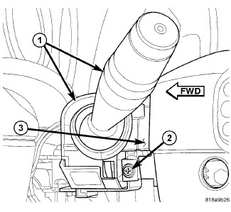
- Remove the screw (2) that secures the left multi-function switch (1) to the mounting bracket integral to the left side of the clockspring (3) on the steering column.
- Slide the switch away from the clockspring far enough to disengage the slide tabs on the switch housing from the channel formations in the mounting bracket.
- Disconnect the jumper wire harness connector from the connector receptacle on the inboard end of the left multi-function switch.
-
Remove the switch from the clockspring.
INSTALLATION
INSTALLATION
To avoid serious or fatal injury on vehicles equipped with airbags, disable the Supplemental Restraint System (SRS) before attempting any steering wheel, steering column, airbag, seat belt tensioner, impact sensor or instrument panel component diagnosis or service. Disconnect and isolate the battery negative (ground) cable, then wait two minutes for the system capacitor to discharge before performing further diagnosis or service. This is the only sure way to disable the SRS. Failure to take the proper precautions could result in accidental airbag deployment.
WARNING:
|
- Position the left multi-function switch (1) close enough to the mounting bracket (3) integral to the left side of the clockspring to reconnect the jumper wire harness connector to the connector receptacle on the inboard side of the switch housing.
- Align the slide tabs on the switch housing with the channel formations integral to the clockspring mounting bracket, then slide the switch into the bracket until it is firmly seated.
- Install and tighten the screw (2) that secures the mounting tab on the front of the left multi-function switch to the mounting bracket on the clockspring. Tighten the screw to 1 N·m (10 in. lbs.).
- Reconnect the instrument panel wire harness connector to the connector receptacle on the back of the switch housing.
- Reinstall the upper and lower shrouds onto the steering column. (Refer to 19 - Steering/Column - Installation) .
-
Reconnect the battery negative cable.