SENSOR, Tire Pressure Monitoring (TPM)
CAUTION
CAUTION
The use of tire sealants is not
recommended for vehicles equipped with the Tire Pressure Monitoring
system. Tire sealants may clog tire pressure sensors.
CAUTION:
Tire pressure sensor valve stem
caps and cores are specially designed for the sensors. Due to risk
of corrosion, do not use a standard valve stem cap or core in a tire
pressure sensor in place of the original equipment style sensor cap
and core.
CAUTION:
It is not recommended to install
a tire pressure sensor in an aftermarket wheel. Use tire pressure
sensors in original style factory wheels only.
CAUTION:
Any time a sensor is to be reinstalled
in a wheel, a new valve stem assembly must be installed to ensure
air tight sealing.
CAUTION:
| NOTE: |
TPM thresholds have been established for the original tire size equipped on the vehicle. Use original size tires only to maintain system accuracy. |
DESCRIPTION
DESCRIPTION
 |
| NOTE: |
Replace the valve stem assembly and tire pressure sensor mounting screw with each tire change. |
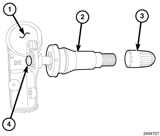
One tire pressure sensor (1) is mounted to a valve stem (2) specifically designed for mounting the pressure sensor (1) in each wheel in place of the traditional tire valve stem. Each sensor has an internal battery that lasts up to 10 years. The battery is not serviceable. At the time of battery failure, the sensor (1) must be replaced. The TPM system operates on a 433 MHz radio frequency. The tire pressure sensor valve stem (2) looks similar to a standard valve stem with the tire mounted on the wheel. To visually identify a tire pressure sensor/valve stem, the valve stem cap (3) is longer than a standard valve stem.
| NOTE: |
This vehicle uses the 433 MHz TPM sensor. Although 315 MHz and 433 MHz sensors are identical in size and shape, they are not interchangeable. Always make sure the correct sensor is being used. A RKE-TPM Analyzer can be used to determine the sensor’s frequency without having to dismount the tire. |
The TPM sensors are designed for original style factory wheels. It is not recommended to install a tire pressure sensor in an aftermarket wheel. (This could cause sealing and system performance issues.)
The serviceable components of the tire pressure sensor are:
- Tire pressure sensor (1), including all components below
- Valve stem (2), including screw (4), core, and cap (3)
- Valve stem core (not shown)
- Valve stem cap (3)
The valve stem caps and cores used are specifically designed for the tire pressure monitoring sensors. Although similar to standard valve stem caps and cores, they are different. The valve stem cap has a special seal inside to keep moisture and corrosion out. The valve stem core has a special nickel coating to protect from corrosion.
OPERATION
OPERATION
The TPMS has been optimized for
the original equipment tires and wheels. TPMS pressures have been
established for the tire size equipped on your vehicle. Undesirable
system operation or sensor damage may result when using replacement
equipment that is not of the same size, type, and/or style. After-market
wheels can cause sensor damage. Do not use aftermarket tire sealants
or balance beads if your vehicle is equipped with a TPMS, as damage
to the sensors may result.
CAUTION:
After inspecting or adjusting
the tire pressure always reinstall the valve stem cap. This will prevent
moisture and dirt from entering the valve stem, which could damage
the Tire Pressure Monitoring Sensor.
CAUTION:
Tire pressure sensor valve stem
caps and cores are specially designed for the sensors. Due to risk
of corrosion, do not use a standard valve stem cap or core in a tire
pressure sensor in place of the original equipment style sensor cap
and core.
CAUTION:
Any time a sensor is to be reinstalled
in a wheel, a new valve stem assembly must be installed to ensure
air tight sealing.
CAUTION:
| NOTE: |
TPM thresholds have been established for the original tire size equipped on the vehicle. Use original size tires only to maintain system accuracy. |
The battery operated tire pressure sensor is both a transmitter and a receiver. The TPM sensor can be forced to transmit if using a special tool such as a TPM-RKE Analyzer. The TPM-RKE Analyzer has the ability to change the sensor mode and to diagnose a faulty TPM sensor. Using a TPM-RKE Analyzer can take up to a minute to force a transmission from a sensor.
Each sensor’s (transmitter) broadcast is uniquely coded so that the module can monitor the state of each of the sensors on the four rotating road wheels. The module can automatically learn and store the sensor’s ID while driving “within 10 minutes continuously above 15 m.p.h. (24 Km/h)” after a sensor has been replaced. The vehicle must be stationary for more then 20 minutes in order to initiate the learning sequence.
The sensor IDs can also be programmed using the TPM-RKE Analyzer Tool. Scan each TPM sensor at each road wheel, and store each Sensor ID in the correct location. (LEFT FRONT, LEFT REAR, RIGHT FRONT, and RIGHT REAR) Connect the TPM-RKE Analyzer Tool to the Scan Tool. Then follow the programming steps outlined in the diagnostic Scan Tool for “Program Tire Pressure Sensor ID w/ TPM Tool” .
DIAGNOSIS AND TESTING - TIRE PRESSURE SENSOR
DIAGNOSIS AND TESTING - TIRE PRESSURE SENSOR
| NOTE: |
Tire pressure may increase from 2 to 6 psi (14 to 41 kPa) during normal driving conditions. Do NOT reduce this normal pressure build up. |
| NOTE: |
Tire pressure will vary with temperature by about 1 psi (6.9 kPa) for every 12 F° (6.5 C). This means that when the outside temperature decreases, the tire pressure will also decrease. Tire pressure should always be set based on cold inflation tire pressure. |
When diagnosing a tire pressure issue, always check air pressure in the tires first with a known accurate air gauge. Adjust air pressure as necessary to that listed on the Tire Inflation Pressure Label (Placard) provided with the vehicle (usually applied to the driver’s side B-pillar). After adjusting air pressure in a tire on the vehicle, allow approximately two minutes for the message or indicator lamp to go out.
Check the tire pressure indicator lamp in the instrument cluster. If the lamp is illuminating continuously, inspect all the tires for leaks. A water “dunk tank” or other water test may be used to check for leaks around the sensor as long as any water at the valve core is removed once the procedure is completed. The water can be easily expelled from the core area by pushing in on the core for several seconds, allowing escaping air to drive out any moisture. Reinflate the tire as necessary. Always make sure the original valve stem cap is securely installed to keep moisture out of the sensor. If the gauge-read pressure in the tires does not indicate a tire pressure issue, refer to the appropriate diagnostic information.
If the indicator lamp is flashing on/off for 75 seconds and then remains on solid, a system fault was detected. Refer to the appropriate diagnostic information.
REMOVAL
REMOVAL
- Raise and support vehicle (Refer to 04 - Vehicle Quick Reference/Hoisting - Standard Procedure) .
-
Remove tire and wheel
assembly.
CAUTION: The cap used on this valve stem contains an O-ring seal to prevent contamination and moisture from entering the valve stem. Do not substitute a regular valve stem cap in its place.
-
Dismount tire from
wheel following tire changer manufacturers instructions while paying
special attention to the following to avoid damaging the pressure
sensor:
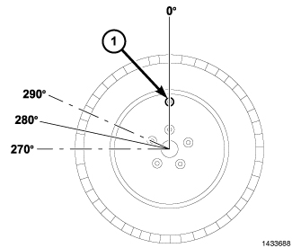
- When breaking the tire bead loose from the wheel rim, avoid using the Bead Breaker in the area of the sensor (1). That includes both outer and inner beads of the tire.
-
When preparing to dismount
the tire from the wheel, carefully insert the mounting/dismounting
tool 280° from the valve stem ± 10°, then proceed to dismount the
tire from the wheel. Use this process on both outer and inner tire
beads.
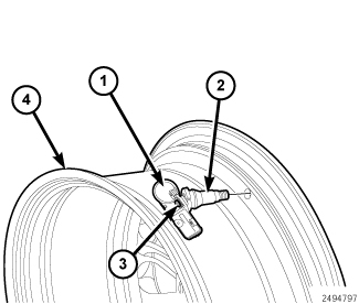
- Remove the sensor to valve stem retainer screw (3) and remove the sensor (1) from the valve stem (2).
-
Remove the valve stem
(2) from the wheel (4).
INSTALLATION
INSTALLATION
| NOTE: |
If replacing tire pressure sensor, a new valve stem will be pre-mounted to the sensor as an assembly. Verify that the sensor is positioned properly before seating the valve stem. If replacing a valve stem only (using the existing tire pressure sensor), the new valve stem will include a new tire pressure sensor mounting screw. Always use a new mounting screw when attaching a sensor to a valve stem. |
|
Any time a sensor is to be reinstalled
in a wheel, a new valve stem assembly must be installed to ensure
air tight sealing.
CAUTION:
-
Wipe area clean around sensor/valve stem mounting hole in wheel (4). Make sure surface of wheel is not damaged.
NOTE: A new valve stem is pre-lubricated for proper installation with a standard tool.
NOTE: If replacing tire pressure sensor, a new valve stem will be pre-mounted to the sensor as an assembly. Verify that the sensor is positioned properly before seating the valve stem.
-
Insert valve stem (2) through wheel (4) and pull through to seat with standard valve stem installation tool.
-
If replacing the valve stem (2) only (using the existing tire pressure sensor), verify that the flat sides of the brass extension on the bottom of the valve stem (2) are at a 90 degree angle with the wheel. Position the pressure sensor (1) over the brass extension, install the retainer screw (4) and tighten to 1.4 N·m (12 in. lbs.).
-
Mount tire on wheel following tire changer manufacturers instructions, paying special attention to the following to avoid damaging tire pressure sensor:
-
Rotating Wheel Tire Changers - Once the wheel is mounted to the changer, position the sensor valve stem (2) approximately 280° from the head of the changer (located at 1) in a clockwise direction before rotating the wheel (also in a clockwise direction) to mount the tire. Use this procedure on both the outer and inner tire beads.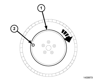
-
Rotating Tool Tire Changers - Position the wheel on the changer so that the sensor valve stem (1) is located approximately 210° clockwise from the installation end of the mounting/dismounting tool (2) once the tool is mounted for tire installation. Make sure the sensor is clear of the lower bead breaker area (3) to avoid damaging the sensor when the breaker rises. Rotate the tool (2) in a counterclockwise direction to mount the tire. Use this procedure on both the outer and inner tire beads.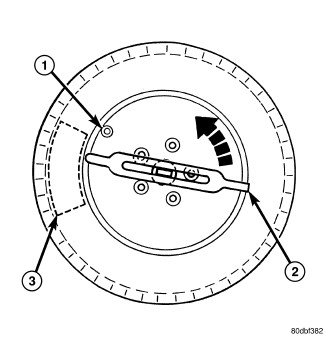
- Adjust air pressure to that listed on Tire Inflation Pressure Label (Placard) provided with vehicle (usually applied to driver's side B-pillar). Make sure original style valve stem cap is securely installed to keep moisture out of sensor.
- Install tire and wheel assembly on the vehicle.
- Remove the support and lower the vehicle.
- Perform one of the following to make the system learn the new sensor ID.
- Use the TPM-RKE Analyzer, 9936, with the Scan Tool to program the WCM with the tire pressure sensor ID (this is part of the TPM Diagnostic Verification Test) (Refer to 28 - DTC-Based Diagnostics/MODULE, Wireless Control (WCM) - Standard Procedure)
- Once the vehicle has remained stationary for more than 20 minutes, drive vehicle for a minimum of 10 minutes while maintaining a continuous speed above 15 mph (24 km/h). During this time, the system will learn the new sensor ID (this is part of the TPM Diagnostic Verification Test) (Refer to 28 - DTC-Based Diagnostics/MODULE, Wireless Control (WCM) - Standard Procedure).
-
| NOTE: |
If a sensor cannot be trained, refer to appropriate diagnostic information. |