Propeller Shaft
- DIAGNOSIS AND TESTING - PROPELLER SHAFT
- STANDARD PROCEDURE - PROPELLER SHAFT ANGLE
- SPECIFICATIONS
- SPECIAL TOOLS
DIAGNOSIS AND TESTING - PROPELLER SHAFT
VIBRATION
Tires that are out-of-round,or wheels that are unbalanced, will cause a low frequency vibration.
Brake drums/rotors that are unbalanced will cause a harsh, low frequency vibration.
Driveline vibration can also result from loose or damaged engine mounts.
Propeller shaft vibration increases as the vehicle speed is increased. A vibration that occurs within a specific speed range is not usually caused by a propeller shaft being unbalanced. Defective universal/CV joints, or an incorrect propeller shaft angle, are usually the cause of such a vibration.
DRIVELINE VIBRATION
|
Drive Condition |
Possible Cause |
Correction |
|---|---|---|
|
Propeller Shaft Noise |
1) Undercoating or other foreign material on shaft. |
1) Clean exterior of shaft and wash with solvent. |
|
2) Loose flange bolts. |
2) Install new bolts and tighten to proper torque. |
|
|
3) Loose or bent flange or excessive runout. |
3) Install new flange. |
|
|
4) Incorrect driveline angularity. |
4) Measure and correct driveline angles. |
|
|
5) Worn U-joint/CV bearings. |
5) Install new propeller shaft. |
|
|
6) Propeller shaft damaged or out of balance. |
6) Install new propeller shaft. |
|
|
7) Broken rear spring. |
7) Install new rear spring. |
|
|
8) Excessive runout or unbalanced condition. |
8) Re-index propeller shaft, test, and evaluate. |
|
|
9) Excessive drive pinion gear shaft runout. |
9) Re-index propeller shaft and evaluate. |
|
|
10) Excessive axle flange deflection. |
10) Inspect and replace flange if necessary. |
|
|
12) Excessive transfer case runout. |
12) Inspect and repair as necessary. |
|
|
Universal Joint /CV Noise |
1) Loose clamping bolts. |
1) Install new bolts and tighten to proper torque. |
BALANCE
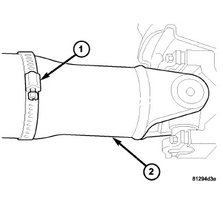 |
If propeller shaft is suspected of being out of balance, use the following procedure.
| NOTE: |
Indexing propeller shaft 180 degrees relative to the yoke may eliminate some vibrations. |
- Raise and support vehicle.
- Clean all foreign material from the propeller shaft.
- Inspect propeller shaft for missing balance weights, broken welds and bent areas. If propeller shaft is bent, it must be replaced.
- Inspect universal joints/CV joints for wear.
- Check propeller shaft bolt torques.
- Remove wheels and install lug nuts to retain brake rotors.
- Mark and number the shaft six inches from the pinion flange end at four positions 90 degrees apart.
- Run and accelerate vehicle until vibration occurs. Note at what speed the vibration occurred. Stop the engine.
-
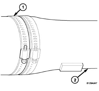
Install a screw clamp at position (1).
-
Start engine and check vibration. If there is little or no change move the clamp to the next positions and repeat vibration test.
NOTE: If there is no difference in vibration at this positions, the vibration may not be the propeller shaft.
-
If vibration decreased, install a second clamp (1) and repeat the test.
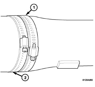
- If additional clamp causes an additional vibration, separate the clamps 1/2 inch (1) above and below the mark. Repeat the vibration test .
- Increase distance between the clamp screws (1) (2) and repeat test, until the least amount of vibration is noticed. Bend the slack end of the clamps so screws will not loosen.
-
If vibration remains unacceptable, repeat the procedure to the front end of the propeller shaft.
RUNOUT
- Remove dirt, rust, paint, and undercoating from the propeller shaft surface where the dial indicator will contact the shaft.
- The dial indicator must be installed perpendicular to the shaft surface.
- Measure runout at the center and ends of the shaft sufficiently far away from weld areas to ensure that the effects of the weld process will not enter into the measurements.
- Refer to Runout Specifications chart.
- If the propeller shaft runout is out of specification, remove the propeller shaft, index the shaft 180°, and re-install the propeller shaft. Measure shaft runout again.
- If the propeller shaft runout is now within specifications, mark the shaft and yokes for proper orientation.
- If the propeller shaft runout is not within specifications, verify that the runout of the transmission/transfer case and axle are within specifications. Correct as necessary and re-measure propeller shaft runout.
- Replace the propeller shaft if the runout still exceeds the limits.
RUNOUT SPECIFICATIONS
|
RUNOUT SPECIFICATIONS |
||
|---|---|---|
|
Front of Shaft |
0.020 in. (0.50 mm) |
|
|
Center of Shaft |
0.025 in. (0.63 mm) |
|
|
Rear of Shaft |
0.020 in. (0.50 mm) |
|
|
||
STANDARD PROCEDURE - PROPELLER SHAFT ANGLE
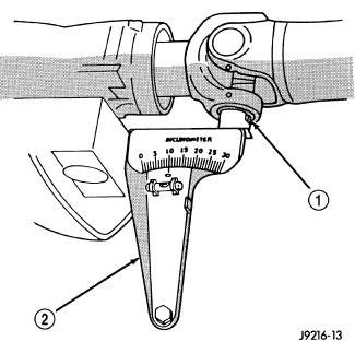 |
To obtain front (output) angle on a C/V propeller shaft, place Inclinometer 7663 on the machined ring of the pinion flange. To obtain propeller shaft angle measurement on the C/V front propeller shaft, place inclinometer on the propeller shaft tube. To obtain rear (output) angle on rear propeller shaft use transfer case/transmission flange.
- Raise and support the vehicle at the axles as level as possible. Allow the wheels and propeller shaft to turn.
- Remove universal joint snap rings if equipped, so inclinometer base sits flat.
-
Rotate shaft until transmission/transfer case output yoke bearing cap is facing downward.
NOTE: Always make measurements from front to rear and from the same side of the vehicle.
-
Place inclinometer (2) on yoke bearing cap (1) or pinion flange ring parallel to the shaft. Center bubble in sight glass and record measurement. This measurement will give you the transmission or Output Yoke Angle (A).
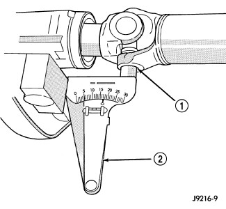
- Rotate propeller shaft 90 degrees and place inclinometer (2) on yoke bearing cap (1) or propeller shaft tube on C/V propeller shaft, parallel to the shaft. Center bubble in sight glass and record measurement. This measurement can also be taken at the rear end of the shaft. This measurement will give you the propeller shaft angle (C)
-
Subtract smaller figure from larger (C minus A) to obtain transmission output operating angle.
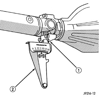
- Rotate propeller shaft 90 degrees and place inclinometer (2) on pinion yoke bearing cap (1) parallel to the shaft. Center bubble in sight glass and record measurement. This measurement will give you the pinion shaft or input yoke angle (B).
-
Subtract smaller figure from larger (C minus B) to obtain axle Input Operating Angle.
RULES
Good cancellation of U-joint operating angles is within 1degree.
Operating angles less than 3 degrees (U-joint system).
Operating angles less than 10 degrees for constant velocity joint.
At least 1/2 of one degree continuous operating (propeller shaft) angle. On one U-joint system less than 1 1/2 degree operating angle.
SPECIFICATIONS
TORQUE SPECIFICATIONS
| DESCRIPTION | N·m |
Ft. Lbs. |
In. Lbs. |
|---|---|---|---|
|
Front Shaft - Axle Flange Bolts |
121 |
89 |
- |
|
Front Shaft - Transfer Case Flange Bolts |
20 |
15 |
- |
|
Rear Shaft - Axle Flange Bolts |
20 |
15 |
- |
|
Rear Shaft - Transfer Case Flange Bolts |
20 |
15 |
- |
SPECIAL TOOLS
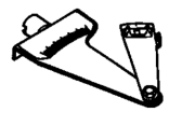 |
7663 - Inclinometer Originally Shipped In Kit Number(s) 7663-MC, XJ594. |