05 - Brakes, ABS
- DESCRIPTION
- OPERATION
- DIAGNOSIS AND TESTING - ANTILOCK BRAKES
- STANDARD PROCEDURE - ANTILOCK BRAKE SYSTEM BLEEDING
- SPECIFICATIONS
DESCRIPTION
| NOTE: |
The Electronic Stability Control (ESC) may also be referred to as Electronic Stability Program (ESP) depending on the vehicle model year and configuration. Certain components may also reference ESP, ESC, or use the traction control symbol. |
The ESC system enhances directional control and stability of the vehicle under various driving conditions. Electronic Stability Control (ESC) corrects for over/under steering of the vehicle by applying the brake of the appropriate wheel to assist in counteracting the over/under steer condition. Engine power may also be reduced to help the vehicle maintain the desired path. The ESC system uses sensors in the vehicle to determine the vehicle path intended by the driver and compares it to the actual path of the vehicle. When the actual path does not match the intended path, ESC applies the brake of the appropriate wheel to assist in counteracting the oversteer or understeer condition
OPERATION
| NOTE: |
The Electronic Stability Control (ESC) may also be referred to as Electronic Stability Program (ESP) depending on the vehicle model year and configuration. Certain components may also reference ESP, ESC, or use the traction control symbol. |
The Anti-Lock Brake System (ABS) has multiple subsystems including, Traction Control System (TCS), Brake Assist System (BAS), Electronic Stability Control (ESC), Hill Start Assist (HSA), Electronic Roll Mitigation (ERM), Trailer Sway Control (TSC), and Hill Descent Control (HDC). All of these systems work together to enhance vehicle stability and control in various driving conditions. A brief explanation of each subsystem follows:
TRACTION CONTROL (TCS)
This system monitors the amount of wheel spin of each of the driven wheels. If wheel spin is detected, brake pressure is applied to the slipping wheel(s) to provide enhanced acceleration and stability.
BRAKE ASSIST SYSTEM (BAS)
The BAS is designed to optimize the vehicle’s braking capability during emergency braking maneuvers. The system detects an emergency braking situation by sensing the rate and amount of brake application and then applies optimum pressure to the brakes.
ELECTRONIC STABILITY CONTROL (ESC)
The ESC system enhances directional control and stability of the vehicle using steering wheel angle, yaw (turning) rate and lateral acceleration sensors (combined into Dynamics Sensor). Using signals from these sensors, in addition to individual wheel speed sensor signals the ESC corrects for over/under steering of the vehicle by applying the brake of the appropriate wheel to assist in counteracting an over/under steer condition. Engine power may also be reduced to help the vehicle maintain the desired path.
HILL START ASSIST
The HSA system is designed to maintain the level of brake pressure for a short period of time after the brake pedal is released so that the vehicle does not roll on a hill between releasing the brake pedal and applying the accelerator pedal. The following must be true for HSA to activate:
- The vehicle must be stopped with the brake applied
- The vehicle must be at a eight percent or greater incline (three percent for manual transmissions)
- Gear selection must match uphill direction (forward gear for uphill, reverse for backing uphill)
| NOTE: |
The HSA system does not operate on an automatic transmission vehicle in the neutral position. |
ELECTRONIC ROLL MITIGATION (ERM)
The ERM system monitors steering wheel input and the speed of the vehicle. When the rate of change of the steering wheel angle and vehicle’s speed are sufficient to potentially cause wheel lift, the appropriate brake will apply and engine power may be reduced to lessen the chance that wheel lift will occur. ERM will only intervene during very severe or evasive driving maneuvers.
TRAILER SWAY CONTROL (TSC)
The TSC system uses sensors in the vehicle to recognize an excessively swaying trailer and will take the appropriate actions to attempt to stop the sway. The system may reduce engine power and apply the brake of the appropriate wheel(s) to counteract the sway of the trailer. TSC will become active automatically once an excessively swaying trailer is recognized
HILL DESCENT CONTROL (HDC)
The HDC system maintains vehicle speed while descending hills in off-road driving conditions by applying the brakes when necessary. HDC can only be enabled when the transfer case is in the “4WD LOW” position and the vehicle speed is less then 48 km/h (30 mph). If these conditions are not met while attempting to use the HDC feature, the HDC indicator light will flash on/off. The HDC indicator lamp will be on solid when HDC is enabled. When enabled, HDC senses the terrain and activates when the vehicle is descending a hill. HDC is only intended for low speed off-road driving. The accelerator pedal will override HDC at any time. Approximate HDC set speeds are as follows:
DIAGNOSIS AND TESTING - ANTILOCK BRAKES
The ABS brake system performs several self-tests every time the ignition switch is turned on and the vehicle is driven. The CAB monitors the systems input and output circuits to verify the system is operating correctly. If the on board diagnostic system senses that a circuit is malfunctioning the system will set a trouble code in its memory.
| NOTE: |
An audible noise may be heard during the self-test. This noise should be considered normal. |
STANDARD PROCEDURE - ANTILOCK BRAKE SYSTEM BLEEDING
The base brake's hydraulic system must be bled anytime air enters the hydraulic system. The ABS must always be bled anytime it is suspected that the HCU has ingested air.
Brake systems with ABS must be bled as two independent braking systems. The non-ABS portion of the brake system with ABS is to be bled the same as any non-ABS system.
The ABS portion of the brake system must be bled separately. Use the following procedure to properly bleed the brake hydraulic system including the ABS.
| NOTE: |
During the brake bleeding procedure, be sure the brake fluid level remains close to the FULL level in the master cylinder fluid reservoir. Check the fluid level periodically during the bleeding procedure and add Mopar® DOT 3 brake fluid as required. |
BLEEDING
When bleeding the ABS system, the following bleeding sequence must be followed to insure complete and adequate bleeding.
- Make sure all hydraulic fluid lines are installed and properly torqued.
- Connect the scan tool to the diagnostics connector. The diagnostic connector is located under the lower steering column cover to the left of the steering column.
-
Using the scan tool, check to make sure the ABM does not have any fault codes stored. If it does, clear them.
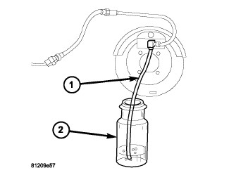
WARNING: When bleeding the brake system wear safety glasses. A clear bleed tube (1) must be attached to the bleeder screws and submerged in a clear container filled part way with clean brake fluid (2). Direct the flow of brake fluid away from yourself and the painted surfaces of the vehicle. Brake fluid at high pressure may come out of the bleeder screws when opened.
NOTE: Pressure bleeding is recommended to bleed the base brake system to ensure all air is removed from system. Manual bleeding may also be used, but additional time is needed to remove all air from system.
- Bleed the base brake system. (Refer to 05 - Brakes - Standard Procedure)
- Using the scan tool, select ECU VIEW, followed by ABS MISCELLANEOUS FUNCTIONS to access bleeding. Follow the instructions displayed. When finished, disconnect the scan tool and proceed.
- Bleed the base brake system a second time. Check brake fluid level in the reservoir periodically to prevent emptying, causing air to enter the hydraulic system.
- Fill the master cylinder fluid reservoir to the FULL level.
- Test drive the vehicle to be sure the brakes are operating correctly and that the brake pedal does not feel spongy.
SPECIFICATIONS
| DESCRIPTION | N·m |
Ft. Lbs. |
In. Lbs. |
|---|---|---|---|
|
Hydraulic Control Unit Bracket to HCU Bolts |
6.5 |
— |
57 |
|
Hydraulic Control Unit Body Bracket Bolts |
16-24 |
— |
142-212 |
|
HCU to Body Bracket Bolts |
9-13 |
— |
80-115 |
|
Hydraulic Control Unit Brake Lines |
15-18 |
— |
130-160 |
|
Antilock Brake Module (ABM) Mounting Bolt |
7-9 |
— |
60-80 |
|
Dynamics Sensor Mounting Nuts |
11 |
8 |
97 |
|
Front Wheel Speed Sensors Mounting Bolt |
4-6 |
— |
34-50 |
|
Rear Wheel Speed Sensors Mounting Bolt |
12-14 |
— |
106-124 |
| Front Brake Lines to Hydraulic Control Unit | 25 | 18 | — |
| Rear Brake Lines to Hydraulic Control Unit | 20 | 15 | — |
| Primary Brake Lines to Hydraulic Control Unit | 27 | 20 | — |
| Secondary Brake Lines to Hydraulic Control Unit | 25 | 18 | — |