05 - Brakes, Base
- WARNING
- DESCRIPTION
- DIAGNOSIS AND TESTING - BASE BRAKE SYSTEM
- MANUAL BLEEDING
- PRESSURE BLEEDING
- BASE BRAKES
- TORQUE CHART
- SPECIAL TOOLS
WARNING
Chrysler LLC does not manufacture
any vehicles or replacement parts that contain asbestos. Aftermarket
products may or may not contain asbestos. Refer to aftermarket product
packaging for product information. Whether the product contains asbestos
or not, dust and dirt can accumulate on brake parts during normal
use. Follow practices prescribed by appropriate regulations for the
handling, processing and disposing of dust and debris.
WARNING:
Never use gasoline, kerosene,
alcohol, motor oil, transmission fluid, or any fluid containing mineral
oil to clean the system components. These fluids damage rubber cups
and seals. Use only fresh brake fluid or Mopar brake cleaner to clean
or flush brake system components. These are the only cleaning materials
recommended. If system contamination is suspected, check the fluid
for dirt, discoloration, or separation into distinct layers. Also
check the reservoir cap seal for distortion. Drain and flush the system
with new brake fluid if contamination is suspected.
CAUTION:
Use Mopar brake fluid, or an equivalent
quality fluid meeting SAE/DOT standards J1703 and DOT 3. Brake fluid
must be clean and free of contaminants. Use fresh fluid from sealed
containers only to ensure proper antilock component operation.
CAUTION:
Use Mopar multi-mileage or high
temperature grease to lubricate caliper slide surfaces, drum brake
pivot pins, and shoe contact points on the backing plates. Use multi-mileage
grease or GE 661 or Dow 111 silicone grease on caliper slide pins
to ensure proper operation.
CAUTION:
DESCRIPTION
Power assist front disc and rear drum brakes are standard equipment. Disc brake components consist of single piston calipers and ventilated rotors. Rear drum brakes are dual shoe units with cast brake drums.
The parking brake mechanism is lever and cable operated. The cables are attached to levers on the rear drum brake secondary shoes. The parking brakes are operated by a hand lever.
A dual diaphragm vacuum power brake booster is used for all applications. All models have an aluminum master cylinder with plastic reservoir.
Factory brake lining on all models consists of an organic base material combined with metallic particles. The original equipment linings do not contain asbestos.
| NOTE: |
LHD shown in graphics. The removal and installation procedures and torques specifications are the same for the RHD. |
DIAGNOSIS AND TESTING - BASE BRAKE SYSTEM
Base brake components consist of the brake shoes, calipers, wheel cylinders, brake drums, rotors, brake lines, master cylinder, booster, and parking brake components.
Brake diagnosis involves determining if the problem is related to a mechanical, hydraulic, or vacuum operated component.
The first diagnosis step is the preliminary check.
PRELIMINARY BRAKE CHECK
- Check condition of tires and wheels. Damaged wheels and worn, damaged, or underinflated tires can cause pull, shudder, vibration, and a condition similar to grab.
- If complaint was based on noise when braking, check suspension components. Jounce front and rear of vehicle and listen for noise that might be caused by loose, worn or damaged suspension or steering components.
-
Inspect brake fluid level and condition. Note that the front disc brake reservoir fluid level will decrease in proportion to normal lining wear. Also note that brake fluid tends to darken over time. This is normal and should not be mistaken for contamination.
- If fluid level is abnormally low, look for evidence of leaks at calipers, wheel cylinders, brake lines, and master cylinder.
- If fluid appears contaminated, drain out a sample. System will have to be flushed if fluid is separated into layers, or contains a substance other than brake fluid. The system seals and cups will also have to be replaced after flushing. Use clean brake fluid to flush the system.
- Check parking brake operation. Verify free movement and full release of cables and pedal. Also note if vehicle was being operated with parking brake partially applied.
- Check brake pedal operation. Verify that pedal does not bind and has adequate free play. If pedal lacks free play, check pedal and power booster for being loose or for bind condition. Do not road test until condition is corrected.
- If components checked appear OK, road test the vehicle.
ROAD TESTING
- If complaint involved low brake pedal, pump pedal and note if it comes back up to normal height.
- Check brake pedal response with transmission in Neutral and engine running. Pedal should remain firm under constant foot pressure.
- During road test, make normal and firm brake stops in 25-40 mph range. Note faulty brake operation such as low pedal, hard pedal, fade, pedal pulsation, pull, grab, drag, noise, etc.
PEDAL FALLS AWAY
A brake pedal that falls away under steady foot pressure is generally the result of a system leak. The leak point could be at a brake line, fitting, hose, or caliper/wheel cylinder. Internal leakage in the master cylinder caused by worn or damaged piston cups, may also be the problem cause.
If leakage is severe, fluid will be evident at or around the leaking component. However, internal leakage in the master cylinder may not be physically evident.
LOW PEDAL
If a low pedal is experienced, pump the pedal several times. If the pedal comes back up, worn lining, rotors, or drums are the most likely causes.
SPONGY PEDAL
A spongy pedal is most often caused by air in the system. However, thin brake drums or substandard brake lines and hoses can also cause a spongy pedal. The proper course of action is to bleed the system, or replace thin drums and suspect quality brake lines and hoses.
HARD PEDAL OR HIGH PEDAL EFFORT
A hard pedal or high pedal effort may be due to lining that is water soaked, contaminated, glazed, or badly worn. The power booster or check valve could also be faulty.
PEDAL PULSATION
Pedal pulsation is caused by components that are loose, or beyond tolerance limits.
The primary cause of pulsation are disc brake rotors with excessive lateral runout or thickness variation, or out of round brake drums. Other causes are loose wheel bearings or calipers and worn, damaged tires.
| NOTE: |
Some pedal pulsation may be felt during ABS activation. |
BRAKE DRAG
Brake drag occurs when the lining is in constant contact with the rotor or drum. Drag can occur at one wheel, all wheels, fronts only, or rears only.
Drag is a product of incomplete brake shoe release. Drag can be minor or severe enough to overheat the linings, rotors and drums.
Minor drag will usually cause slight surface charring of the lining. It can also generate hard spots in rotors and drums from the overheat-cool down process. In most cases, the rotors, drums, wheels and tires are quite warm to the touch after the vehicle is stopped.
Severe drag can char the brake lining all the way through. It can also distort and score rotors and drums to the point of replacement. The wheels, tires and brake components will be extremely hot. In severe cases, the lining may generate smoke as it chars from overheating.
Possible causes for brake drag condition are:
- Seized or improperly adjusted parking brake cables.
- Loose/worn wheel bearing.
- Seized caliper or wheel cylinder piston.
- Caliper binding on corroded bushings or rusted slide surfaces.
- Loose caliper mounting bracket.
- Drum brake shoes binding on worn/damaged support plates.
- Mis-assembled components.
If brake drag occurs at all wheels, the problem may be related to a blocked master cylinder return port, or faulty power booster (binds-does not release).
BRAKE FADE
Brake fade is usually a product of overheating caused by brake drag. However, brake overheating and resulting fade can also be caused by riding the brake pedal, making repeated high deceleration stops in a short time span, or constant braking on steep mountain roads. Refer to the Brake Drag information in this section for causes.
BRAKE PULL
Possible causes for front brake pull condition are:
- Contaminated lining in one caliper.
- Seized caliper piston.
- Binding caliper.
- Loose caliper.
- Rusty adapter/caliper slide surfaces.
- Improper brake shoes.
- Damaged rotor.
A worn, damaged wheel bearing or suspension component are further causes of pull. A damaged front tire (bruised, ply separation) can also cause pull.
A common and frequently misdiagnosed pull condition is where direction of pull changes after a few stops. The cause is a combination of brake drag followed by fade at one of the brake units.
As the dragging brake overheats, efficiency is so reduced that fade occurs. Since the opposite brake unit is still functioning normally, its braking effect is magnified. This causes pull to switch direction in favor of the normally functioning brake unit.
An additional point when diagnosing a change in pull condition concerns brake cool down. Remember that pull will return to the original direction, if the dragging brake unit is allowed to cool down (and is not seriously damaged).
REAR BRAKE GRAB OR PULL
Rear grab or pull is usually caused by improperly adjusted or seized parking brake cables, contaminated lining, bent or binding shoes and support plates, or improperly assembled components. This is particularly true when only one rear wheel is involved. However, when both rear wheels are affected, the master cylinder or proportioning valve could be at fault.
BRAKES DO NOT HOLD AFTER DRIVING THROUGH DEEP WATER PUDDLES
This condition is generally caused by water soaked lining. If the lining is only wet, it can be dried by driving with the brakes very lightly applied for a mile or two. However, if the lining is both soaked and dirt contaminated, cleaning and/or replacement will be necessary.
BRAKE SQUEAK/SQUEAL
Brake squeak or squeal may be due to linings that are wet or contaminated with brake fluid, grease, or oil. Glazed linings and rotors with hard spots can also contribute to squeak. Dirt and foreign material embedded in the brake lining will also cause squeak/squeal.
A very loud squeak or squeal is frequently a sign of severely worn brake lining. If the lining has worn through to the brake shoes in spots, metal-to-metal contact occurs. If the condition is allowed to continue, rotors and drums can become so scored that replacement is necessary.
BRAKE CHATTER
Brake chatter is usually caused by loose or worn components, or glazed/burnt lining. Rotors with hard spots can also contribute to chatter. Additional causes of chatter are out-of-tolerance rotors, brake lining not securely attached to the shoes, loose wheel bearings and contaminated brake lining.
THUMP/CLUNK NOISE
Thumping or clunk noises during braking are frequently not caused by brake components. In many cases, such noises are caused by loose or damaged steering, suspension, or engine components. However, calipers that bind on the slide surfaces can generate a thump or clunk noise. In addition, worn out, improperly adjusted, or improperly assembled rear brake shoes can also produce a thump noise.
BRAKE LINING CONTAMINATION
Brake lining contamination is mostly a product of leaking calipers or wheel cylinders, worn seals, driving through deep water puddles, or lining that has become covered with grease and grit during repair. Contaminated lining should be replaced to avoid further brake problems.
WHEEL AND TIRE PROBLEMS
Some conditions attributed to brake components may actually be caused by a wheel or tire problem.
A damaged wheel can cause shudder, vibration and pull. A worn or damaged tire can also cause pull.
Severely worn tires with very little tread left can produce a grab-like condition as the tire loses and recovers traction. Flat-spotted tires can cause vibration and generate shudder during brake operation. A tire with internal damage such as a severe bruise, cut, or ply separation can cause pull and vibration.
MANUAL BLEEDING
 |
Use Mopar brake fluid, or an equivalent quality fluid meeting SAE J1703-F and DOT 3 standards only. Use fresh, clean fluid from a sealed container at all times.
- Remove reservoir filler caps and fill reservoir.
- If calipers were overhauled, open all caliper bleed screws. Then close each bleed screw as fluid starts to drip from it. Top off master cylinder reservoir once more before proceeding.
-
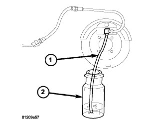
Attach one end of bleed hose (1) to bleed screw and insert opposite end in glass container (2) partially filled with brake fluid. Be sure end of bleed hose is immersed in fluid.
NOTE: Bleed procedure should be in this order (1) Right rear (2) Left rear (3) Right front (4) Left front.
- Open up bleeder, then have a helper press down the brake pedal. Once the pedal is down, hold the pedal down while closing the bleeder. Repeat bleeding until fluid stream is clear and free of bubbles. Then move to the next wheel.
- Before moving the vehicle verify the pedal is firm and not mushy.
-
Top off the brake fluid and install the reservoir cap.
PRESSURE BLEEDING
Use Mopar brake fluid, or an equivalent quality fluid meeting SAE J1703-F and DOT 3 standards only. Use fresh, clean fluid from a sealed container at all times.
Follow the manufacturers instructions carefully when using pressure equipment. Do not exceed the tank manufacturers pressure recommendations. Generally, a tank pressure of 15-20 psi is sufficient for bleeding.
Fill the bleeder tank with recommended fluid and purge air from the tank lines before bleeding.
Do not pressure bleed without a proper master cylinder adapter. The wrong adapter can lead to leakage, or drawing air back into the system.
BASE BRAKES
SPECIFICATIONS
| DESCRIPTION | SPECIFICATION |
|---|---|
|
Front Disc Brake Rotor Type |
Ventilated |
|
Rear Disc Brake Rotor Type |
Solid |
|
Front Disc Brake Rotor Diameter - 16 in. Wheels |
302 mm (11.89 in.) |
|
Front Disc Brake Rotor Diameter - 17 in. Wheels |
332 mm (13.07 in.) |
|
Rear Disc Brake Rotor Diameter |
316 mm (12.44 in.) |
|
Front Ventilated Disc Brake Rotor Max. Runout |
0.020 mm (0.0008 in) |
|
Rear Solid Disc Brake Rotor Max. Runout |
0.020 mm (0.0008 in) |
|
Front Ventilated Disc Brake Rotor Max. Thickness Variation |
0.009 mm (0.00035 in.) |
|
Rear Solid Disc Brake Rotor Max. Thickness Variation |
0.009 mm (0.00035 in.) |
|
Front Ventilated Disc Brake Rotor Min. Thickness |
26.4 mm (1.049 in.) |
|
Rear Solid Disc Brake Rotor Min. Thickness |
10.4 mm (0.409 in.) |
|
Disc Brake Calipers |
Single Piston Floating |
|
Brake Booster |
Dual Diaphragm |
TORQUE CHART
TORQUE
| DESCRIPTION | N·m |
Ft. Lbs. |
In. Lbs. |
|---|---|---|---|
|
Brake Booster Mounting Nuts |
25 |
18 |
— |
|
Master Cylinder Mounting Nuts |
17 |
13 |
151 |
|
Booster Mounting Plate |
18 |
— |
159 |
|
Master Cylinder Brake Lines |
19 |
14 |
168 |
|
Front Caliper Mounting Bolts |
35 |
26 |
— |
|
Rear Caliper Mounting Bolts |
35 |
26 |
220 |
|
Front Caliper Brake Hose Banjo Bolt |
32 |
24 |
— |
|
Rear Caliper Brake Hose Banjo Bolt |
31 |
23 |
— |
|
Front Brake Hose Spring Bracket Bolt |
8 |
— |
71 |
|
Front Brake Line To Hose Tube Nut |
12 |
— |
105 |
|
Front Brake Hose To Frame Routing Clip Bolt |
20 |
— |
177 |
|
Front Caliper Adapter Mounting Bolts |
136 |
100 |
— |
|
Rear Caliper Adapter Mounting Bolts |
105 |
77 |
— |
|
Parking Brake Lever Bracket Bolts |
12 |
9 |
— |
SPECIAL TOOLS
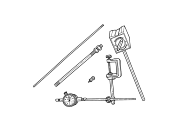 |
C-3339A - Set, Dial Indicator Originally Shipped In Kit Number(s) 9202. |
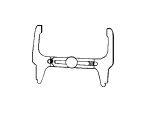 |
C-3919 - Gauge, Brake Shoes |
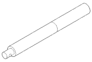 |
C-4171 - Driver Handle, Universal Originally Shipped In Kit Number(s) 9202, 9202A-CAN, 9202CC, 9299, 9299CC, 9299CC, 9300A-CAN. |
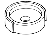 |
C-4842 - Installer, Dust Boot |